background image

8

IOM-T-482

  2125 


© 2021 Watts

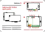
This section explains how to wire individual devices to the 
tN4 Gateway. For step-by-step wiring, refer to the terminal 
number on the right of the page.
•  Before wiring ensure all power is turned off and take all 

necessary precautions.

•  Install the supplied wiring compartment barriers by sliding 

them into the grooves provided to isolate the low and 
high voltage wiring.

•  Refer to the current and voltage ratings at the back of 

this brochure before connecting devices to this control.

•  All wires must be rated at least 300 V.
•  High voltage wires should be 14 AWG conductors.
•  Low voltage wires should be 18 AWG conductors.
•  Strip all wiring to a length of 

3

8

 in. or 10 mm for  

all terminals.

•  Only qualified personnel should attempt installation of  

the tN4 Gateway.

•  Provide a 15 A circuit for the power.
•  An approved circuit breaker or power disconnect that 

de-energizes the high voltage wiring should be located 
near the tN4 Gateway, and marked as the 115 V (ac) 
power disconnect for this device.

•  115 V (ac) high voltage power supply circuits must be 

protected by 15 A maximum overcurrent protection.

•  Connect 115 V (ac) hot (L) to terminal 2.
•  Connect 115 V (ac) neutral (N) to terminal 1.
•  Connect the ground wire to one of the ground screws 

provided in the wiring chamber.

The tN4 Gateway includes five tN4 buses:
•  tN4 Bus 0 (terminals 3 and 4)
•  tN4 Bus 1 (terminals 5 and 6)
•  tN4 Bus 2 (terminals 7 and 8)
•  tN4 Bus 3 (terminals 9 and 10)
•  tN4 Bus 4 (terminals 11 and 12)
Each tN4 bus consists of a tN4 terminal as well as a  
C terminal. 
Polarity is important.
Connect each tN4 bus on the system to a tN4 bus input 
on the 482. The tN4 bus order on the 482 is not critical; 

however, it is recommended to connect them to the  
482 in the same order in order to avoid confusion during 
troubleshooting.

3

4

 0

C0 tN4

C

tN4

The 482 exterior can be cleaned using a damp cloth. Moisten the cloth with water and wring out prior to wiping the 
device. Do not use solvents or cleaning solutions.

1

2

Power

N

L

115 V (ac)

Ground screw

Use a Category 5 cable with an RJ45 connector and plug 
it into the 482 RS 232 serial port. Connect the opposing 
end RJ45 connector into the RJ45 to DB9 adapter.
The adapter uses the following pin connections:
•  Pin 3 - Data Terminal Ready (firmware programming only)
•  Pin 4 - Signal Ground
•  Pin 5 - Receive Data
•  Pin 6 - Transmit Data

Top
View

1

8

Front
View

8

1

tN4 Bus Inputs 

Terminals 3 - 12


     Power Requirements 

Terminals 1-2


Wiring the tN4 Gateway 

Terminals 1-12 

RS 232 Serial Port 


Cleaning 


Summary of Contents for TekmarNet 4

Page 1: ...ion systems Features Installation Operation and Maintenance Manual tekmarNet 4 Gateway 482 IOM T 482 tekmarNet 4 and tekmarNet 2 Compatible CSA C US approved for US and Canada Drivers available for these third party automation systems AMX Clare Controls Control4 Crestron Elan RTI Savant URC and Vantage home automation systems Trademarks are the property of their respective third party WARNING Plea...

Page 2: ... length of each tN4 bus cannot exceed 5000 feet Each tN4 bus consists of a pair of wires tN4 and C The tN4 Gateway can accept up to 5 tN4 buses Use a Category 5 cable up to or less than 150 feet 45 m in length to connect the tN4 Gateway to the home automation equipment To avoid serious personal injury and damage to the equipment Improper installation and operation of this control could result in d...

Page 3: ...rol mount it onto the DIN rail This will be a popular option for those who pre fer to mount the control inside a larger electrical panel The wiring can enter the bottom or the back of the enclosure Knock outs provided in the base allow the wiring to be run in conduit up to the enclosure The base also has holes that line up with the mounting holes of most common electrical boxes Press down at the f...

Page 4: ...d off red red Caution Signal wiring must be rated at least 300 V H2051A Power L 1 N 5 C1 1 6 tN4 3 C0 0 4 tN4 7 C2 2 8 tN4 9 C3 3 10 tN4 11 C4 4 12 tN4 Do not apply power RS 232 Tx Rx To RS 232 Serial Port Adapter 1 Reporting Enable Power On State Off On Description tN4 network of tekmarNet thermostats are connected to a tN4 Gateway 482 Refer to Thermostat wiring brochures for complete wiring sche...

Page 5: ...25 2021 Watts Description A Universal Reset Module 422 and Duel Zone Manager 337 are connected to a tN4 Gateway 482 Refer to W422 and W337 wiring brochures for complete wiring schematic Electrical Application 482 E2 ...

Page 6: ...2125 2021 Watts Electrical Application 482 E3 Description A Universal Reset Module 423 and Power Manager 345 are connected to a tN4 Gateway 482 Refer to W423 and W345 wiring brochures for complete wiring schematics ...

Page 7: ...IOM T 482 2125 2021 Watts Description A tN2 House Control 402 is connected to a tN4 Gateway 482 Refer to the 402 Installation Operation Manual for a complete wiring schematic Electrical Application 482 E4 ...

Page 8: ... terminal 2 Connect 115 V ac neutral N to terminal 1 Connect the ground wire to one of the ground screws provided in the wiring chamber The tN4 Gateway includes five tN4 buses tN4 Bus 0 terminals 3 and 4 tN4 Bus 1 terminals 5 and 6 tN4 Bus 2 terminals 7 and 8 tN4 Bus 3 terminals 9 and 10 tN4 Bus 4 terminals 11 and 12 Each tN4 bus consists of a tN4 terminal as well as a C terminal Polarity is impor...

Page 9: ...is present there is a short circuit fault along the wires It is recommended to replace the tN4 bus wires 5 To test for open circuits Disconnect the tN4 bus wires on one end and connect them together Disconnect the tN4 bus wires on the other end Use an electrical meter to measure for continuity If there is no continuity there is an open circuit fault along the wires It is recommended to replace the...

Page 10: ...er is on Power is off Tx Flashes when RS232 message is sent No RS232 message Rx Flashes when RS232 message is received No RS232 message tN4 Bus 0 tN4 communication on bus 0 b is present No tN4 communication on bus 0 tN4 Bus 1 tN4 communication on bus 1 is present No tN4 communication on bus 1 tN4 Bus 2 tN4 communication on bus 2 is present No tN4 communication on bus 2 tN4 Bus 3 tN4 communication ...

Page 11: ...the thermostat address To determine the thermostat address please consult the data brochure for the appropriate thermostat Example 1 A thermostat with bus and thermostat device number of b 01 is wired to a model 400 controller boiler bus and in turn is wired to the 482 on port 0 This address is 0101 Example 2 A thermostat with bus and thermostat device number of b 24 is wired to a model 423 contro...

Page 12: ...and without limiting the foregoing in any way tekmar is not responsible in contract tort or strict product liability for any other losses costs expenses inconveniences or dam ages whether direct indirect special secondary incidental or conse quential arising from ownership or use of the product or from defects in workmanship or materials including any liability for fundamental breach of contract T...

Reviews: