background image

12

IOM-UpGradeKit-SentryPlusAlert2

  2013 

EDP# 2916013 

© 2020 Watts

Possible Cause 3

Cellular reception might not be supported at your site. 
The Cellular Gateway operates using AT&T LTE Cat-M1. 

Mobile 

phone reception is not a reliable indicator of expected 

signal strength for the Cellular Gateway.

Solution 3

If you cannot find cellular reception anywhere at your site, you 

may not have carrier coverage at your site. Contact Syncta’s 

Customer Support team at 888-725-4285 for more information.
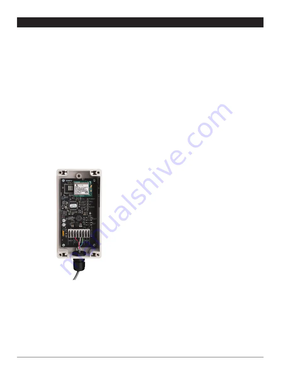
POWER LED is Off

If the POWER LED is off, make sure the Cellular Gateway is 

plugged in and that the power outlet is active, wired to Control 

Box correctly and control box is powered with the provided 

24Vdc power supply. If the device is still not working, review the 

possible cause and solution below.

Possible Cause

If the Cellular Gateway is plugged in and the POWER LED is off, 

the +24Vdc & GND wiring polarity inside the Cellular Gateway 

might have been accidentally swapped.

Solution

Use the instructions below to swap the +24Vdc and GND wiring 

inside the Cellular Gateway.
1.  Remove power from the control box.
2.  Swap places of the wires in the power terminals of the 

Cellular Gateway.

3.  Reapply power to the control box
4.  If the POWER LED is still off, contact Syncta’s Customer 

Support team ([email protected] or 888-725-4285).

No Connection to the Cloud

If the IoT LED is blinking, there is no connection to the Watts Cloud. If the 

device is not working, review the possible cause and solution below.

Possible Cause

There is a disruption in service between the Watts Cloud and the Cellular 

Gateway. 

Solution

Contact Syncta’s Customer Support team ([email protected] or 888-

725-4285) to confirm if the issue is specific to your Cellular Gateway or to 

the cellular service provider. 

Troubleshooting Guide

Summary of Contents for SentryPlus Alert

Page 1: ... the Flood Sensor Backflow RPZ Upgrades 3 2 Installing and Wiring Retrofitting the Control Box 4 5 3 Installing the Cellular Gateway 6 4 Setting Up the Cellular Gateway 6 5 Registering SentryPlus Alert 7 Start up Instructions 7 Overview 8 Startup Sequence 8 LEDs 9 Buttons 10 Terminals 10 Troubleshooting Guide 11 12 Warranty 13 NOTICE Use of the SentryPlus AlertTM technology does not replace the ne...

Page 2: ...ng bracket sold separately Understanding Safety Information This safety alert symbol is shown alone or used with a signal word DANGER WARNING or CAUTION A pictorial and or safety mes sage to identify hazards and alert you to the potential for death or serious personal injury Identifies hazards which if not avoided will result in death or serious injury Identifies hazards which if not avoided could...

Page 3: ...h the bottom of the pipe then pull them up at least The ends of the sensor probes should be located between and of the pipe s inner diameter from the pipe bottom The probes MUST NOT BE less than from the pipe wall Hand tighten the white plastic nuts on the probes to make it water tight Ensure Flood Sensor probes do not contact pipe bottom or sides CAUTION Installation and Operation Flood Sensor To...

Page 4: ...ect to a Building Management System or alarm for remote indications of a continuous water discharge at the terminals labeled REMOTE TRIP There is no polarity 5 Using the four conductor communications cable with the kit connect to the Cellular Gateway using the terminals labeled WIRELESS Insert the cable through the wiring gland and attach one wire to each terminal Cellular Gateway connections will...

Page 5: ... is no polarity 5 The Relay Box includes several spare terminals for your con venience to ease wiring requirements such as building moni toring inputs or valve positioning For New and Existing LFF113RFP Installations 1 Using an electrical cable not provided connect terminals 3 and 4 in the Relay Box to 110VAC power 2 Using a 300 V 14 24 AWG cable not provided connect the Relay Box to the Control B...

Page 6: ...l wiring glands 5 Apply power to the Control Box and Cellular Gateway 1 Start Up Upon start up the POWER LED will light up a steady green to indicate power is supplied The Cellular Gateway will automatically go into its start up sequence During the start up sequence the CELL and IoT LED will blink blue indicating the Cellular Gateway is searching for a cellular connection This may take up to 10 mi...

Page 7: ...8 10 Travel Inches 3 8 3 8 3 8 5 8 3 4 1 11 2 2 21 2 Valve Cover Chamber Capacity VALVE SIZE INCHES 11 4 11 2 2 21 2 3 4 6 8 10 fl oz 4 4 4 10 10 22 70 U S Gal 11 4 21 2 1 Open the Control Box Apply power 2 Pour an adequate amount of water into the RPZ Relief Valve Air Gap until the DELAY counter begins to count down This indicates the Flood Sensor is properly installed and is sensing water in the...

Page 8: ...use information can result in death serious personal injury property damage or damage to the equipment Visit Watts com with any questions Keep this Manual for future reference WARNING Startup Sequence COLOR STATE DEFINITION Steady Green Green LED turns on when power is applied Cell LED blinks Trying to establish a cellular connection IoT LED blinks Trying to establish a connection to the Watts Clo...

Page 9: ...OLOR STATE DEFINITION SOLUTION Steady Blue A cellular connection is present N A Short off blink The cellular connection is poor See Poor or No Cellular Reception on pages 7 8 Blue blinking There is no cellular connection searching See Poor or No Cellular Reception on pages 7 8 IoT The IoT LED indicates whether or not there is a connection to the Cloud COLOR STATE DEFINITION SOLUTION Steady Blue Th...

Page 10: ...ations to cease Note You can also perform a full reset by removing power to the Cellular Gateway for 10 seconds and then plugging it back in TEST Press to have a test notification sent Note The unit must have already been registered and commu nication preferences set for these notifications to be sent Terminals Terminals wire to Control Box PWR GND MOD MOD Terminals labeled INPUT 1 INPUT 2 are res...

Page 11: ...pipes or other obstructions particularly anything metallic Solution 1 Move the Cellular Gateway to a location where the antenna is not facing any internal walls wires pipes or other obstructions such as an electrical box Possible Cause 2 The location has poor cellular reception Solution 2 Move your Cellular Gateway to a different location and check to see that the CELLULAR LED is steady blue if it...

Page 12: ...sible Cause If the Cellular Gateway is plugged in and the POWER LED is off the 24Vdc GND wiring polarity inside the Cellular Gateway might have been accidentally swapped Solution Use the instructions below to swap the 24Vdc and GND wiring inside the Cellular Gateway 1 Remove power from the control box 2 Swap places of the wires in the power terminals of the Cellular Gateway 3 Reapply power to the ...

Page 13: ...13 IOM UpGradeKit SentryPlusAlert2 2013 EDP 2916013 2020 Watts Notes ...

Page 14: ...14 IOM UpGradeKit SentryPlusAlert2 2013 EDP 2916013 2020 Watts Notes ...

Page 15: ...15 IOM UpGradeKit SentryPlusAlert2 2013 EDP 2916013 2020 Watts ...

Page 16: ...duct does not work properly other costs resulting from labor charges delays vandalism negligence fouling caused by foreign material damage from adverse water conditions chemical or any other circumstances over which the Company has no control This warranty shall be invalidated by any abuse misuse misapplication improper installation or improper maintenance or alteration of the product Some States ...

Reviews: