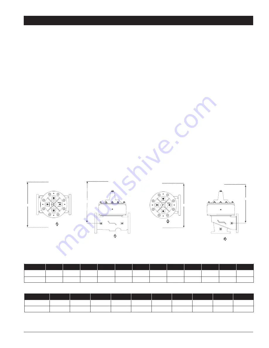
background image

Globe

Angle

Size (in)

2

21/2

3

4

6

8

10

12

14

16

20

24

A (in)

20

22

22

24

32

34

38

44

48

52

56

56

B (in)

20

22

22

25

36

38

40

44

48

50

50

50

Size (in)

2

2


1/2

3

4

6

8

10

12

14

16

C (in)

20

22

22

24

32

34

38

44

48

52

D (in)

20

22

22

25

36

38

40

44

48

50

1.  Prior to installation, flush line to remove debris.

2.  Install valve so the flow arrow matches flow through the line, and gauges to monitor valve inlet and outlet pressures. Install isolation valves 

upstream and downstream of the main valve.

3.  Provide adequate clearance for valve servicing and maintenance. Refer to valve servicing dimensions on next page. Avoid installing valves 

6" and larger in the vertical position (main valve stem horizontal). Automatic Control Valves (ACVs) are designed for horizontal in-line instal-
lation, with the cover facing up (main valve stem vertical). Slow operation or premature stem and guide wear may occur if valve is not 
installed according to factory recommendations. Consult factory for detailed engineering review prior to ordering if valve is to be installed 
other than horizontally in-line.

4.  If valve is equipped with a pilot control system, extra precautions should be made during installation to protect the piping circuit from dam-

age. Only remove the pilot control system from the valve if necessary. Tubing and fittings should be kept clean and replaced exactly as 
removed. Consult appropriate hydraulic schematic to ensure proper re-assembly.

5.  Connect solenoid wiring leads to desired switching device, using safe, standard electrical practices.

6.  Wire the limit switch contacts to the proper relay connections, using safe, standard electrical practices. Adjust the limit switch collar to the 

approximate make/break contact position.

7.  Field install remote operating pressure line, minimum recommended size ½”, to the downstream side of the system check valve. 

8.  After installation, vent entrapped air from valve cover and pilot system by following instructions in the 

Commissioning Deep Well Pump 

Control

 section of the next page.


15


The following tables detail the recommended minimum valve servicing dimensions.

Valve Servicing Dimensions

Start-up of an automatic control valve requires that proper procedures be followed. Time must be allowed for the valve to react to 

adjustments and the system to stabilize. The objective is to bring the valve into service in a controlled manner to protect the system 

from damaging over-pressure.

Installation


B


FLOW

FLOW

FLOW


FLOW

ES-ACV-LFM513-14  2115 

© 2021 Watts

Installation, Operation and Maintenance - Series LFM513-14 

Summary of Contents for LFM513-14 Series

Page 1: ...in accordance with local codes and ordinances WARNING Need for Periodic Inspection Maintenance This product must be tested periodically in compliance with local codes but at least once per year or more as service conditions warrant All products must be retested once maintenance has been performed Corrosive water conditions and or unauthorized adjustments or repair could render the product ineffect...

Page 2: ...an open valve Pump start up When the pump is signaled to start the 4 Way Solenoid is energized and directs fluid and pressure into the cover chamber above the diaphragm and relieves fluid and pressure from the power chamber below the diaphragm The fluid and pressure relieved from the cover chamber is vented to atmosphere or available floor drain The valve closes at an adjustable rate gradually adm...

Page 3: ...aphragm assembly This assembly is the only moving part within the valve allowing it to open or close as commanded by the pilot control system When pressure is applied to the upper diaphragm chamber and released from the lower diaphragm chamber the valve travels to a closed position When pressure is applied to the lower diaphragm chamber and released from the upper diaphragm chamber the valve trave...

Page 4: ...ure Drop psi 2 3 4 6 8 10 20 30 40 60 80 100 Flow Rate Gallons per minute Water 2 4 10 20 40 60 80 100 200 500 1000 2000 5000 10000 20000 100000 8 6 1 4 1 6 1 2 1 0 8 6 4 3 2 1 2 2 1 2 1 0 8 6 4 3 2 1 2 2 Angle Globe C V Suggested Maximum continuous flow based on velocity of 20 ft per second Maximum intermittent flow based on velocity of 25 ft per second Minimum flow rates based on a 20 40 psi pre...

Page 5: ...e Iron 11 Diaphragm Buna N Nitrile 12 Inner Bearing Bolts 3 and Smaller ASTM A276 304 Stainless Steel 13 Inner Bearing Retainer 3 and Smaller ASTM A276 302 Stainless Steel 13A Bearing Retaining Ring 4 and Larger ASTM A276 302 Stainless Steel 14 Inner Bearing ASTM A276 304 Stainless Steel 15 O ring Buna N Nitrile 16 O ring Buna N Nitrile 17 Stem ASTM A276 304 Stainless Steel 18 Disc Retainer ASTM A...

Page 6: ...g Weights A B C D E F G H I J K L M in in mm in mm in mm in mm in mm in mm in mm in mm in mm in mm in in in lbs kgs 2 93 8 238 93 8 238 10 254 9 230 4 120 43 4 121 5 127 31 4 83 31 4 83 31 2 89 3 8 1 2 1 4 45 20 21 2 11 279 11 279 115 8 295 105 16 262 51 2 140 51 2 140 57 8 149 4 102 4 102 45 16 110 1 2 1 2 1 2 70 32 3 121 2 318 12 305 131 4 337 111 2 291 61 4 159 6 152 63 8 162 41 2 114 4 102 43 ...

Page 7: ...EPDM optional Viton optional Voltage 24VDC 24VAC or 120VAC Enclosure General Purpose NEMA 4 standard Explosion Proof NEMA 6 6P 7 9 optional Action 4 Way Actuation Solenoid Action only Main valve action energize to open or energize to close is dependent on the particulars of the pilot system Brass solenoids are not lead free and it is illegal to use them in potable services in the United States suc...

Page 8: ...the valve opens or closes The adjustable collar is normally set to contact the trip arm when the main valve is closed The collar can be positioned on the stem by loosening the set screw to actuate the switch at the desired point of valve travel Single Pole Double Throw Switch Common Lug Normally Open Normally Closed Specifications Body Material Stainless Steel Elastomers Buna N standard EPDM optio...

Page 9: ...n In the free flow direction the seat moves out of the flow path to all unrestricted flow Specifications Standard Flow Control Large Flow Control FLOW FLOW CLOSED Fluid Speed Controlled by Needle FLOW External Threads Internal Threads FLOW OPEN Free Flow Seat Full Open Size Standard Flow MNPT x 3 8 FNPT High Flow 1 2 MxF NPT Body Material Lead Free Brass Stainless Steel optional Seat Lead Free Bra...

Page 10: ...ew clockwise raises the control set point Turning the adjustment screw counterclockwise lowers the control setpoint The LFPV20C is equipped with one 1 2 NPT inlet and outlet port and a 1 4 NPT side sensing port located on the power chamber The 1 4 side sensing port is used to monitor upstream or down stream pressure as required by specific valve function Body Material Lead Free Copper Silicon Allo...

Page 11: ...ilot circuit speed controls and pilots The filter element can be accessed for cleaning by removing the clean out cap or may be cleaned by installing an optional blow down ball valve The wetted surface of this product contacted by consumable water contains less than 0 25 of lead by weight Body Material Lead Free Copper Silicon Alloy CF8M 316 Stainless Steel optional Retainer Cap Lead Free Copper Si...

Page 12: ...re used in pilot lines to provide a positive shutoff in any override or maintenance situation for simple trouble shooting This 2 piece full port valve features bottom loaded stems PTFE seats and packing Size Dimensions Weight C H L in in mm in mm in mm lbs kg 1 4 113 16 46 37 16 87 13 4 45 0 4 0 2 3 8 113 16 46 37 16 87 13 4 45 0 4 0 2 1 2 113 16 46 37 16 87 115 16 50 0 4 0 2 3 4 21 4 57 4 101 25 ...

Page 13: ...r Size 1 4 3 4 NPT Model LF60 Flo Clean Strainers are used to filter the fluid pass ing through the pilot circuit and provide protection to pilot circuit speed controls and pilots It is installed in the inlet body port of the Main Valve exposing the strainer element to main line flow The currents and flow across the screen create a self scouring effect cleaning the filter element The wetted surfac...

Page 14: ...vel Body Material Stainless Steel Elastomers Buna N standard EPDM optional Viton optional Enclosure NEMA 1 3 4 and 13 General Purpose standard NEMA 1 7 and 9 Explosion Proof optional Electrical Form C SPDT Switch 15 amp 125 250 or 480 VAC amp 125 VDC amp 250 VDC Conduit Connection The wetted surface of this product contacted by consumable water contains less than 0 25 of lead by weight Item Descri...

Page 15: ...ion to protect the piping circuit from dam age Only remove the pilot control system from the valve if necessary Tubing and fittings should be kept clean and replaced exactly as removed Consult appropriate hydraulic schematic to ensure proper re assembly 5 Connect solenoid wiring leads to desired switching device using safe standard electrical practices 6 Wire the limit switch contacts to the prope...

Page 16: ...n decrease the rate of opening closing turn the adjustment screws on the speed controls IN clockwise See Figure 2A below STEP 2 Prior to pump start energize the solenoid to confirm connection to power source STEP 3 De energize the solenoid prior to initial pump start STEP 4 Energize the solenoid at pump start to close the main valve checking that the main valve closes STEP 5 Closing Speed Flow Adj...

Page 17: ...s into the lower chamber the Opening speed flow control restricts flow out of the upper cham ber of the main valve If valve opening is too slow turn the adjustment screw OUT counterclockwise increasing the rate of opening If valve opening is too quick turn the adjustment screw IN clock wise decreasing the rate of opening STEP 10 At valve full open position deep well pump will stop Adjust limit swi...

Page 18: ...heets for approximate cover capacity A continuous flow of water from the open port indicates a damaged diaphragm or loose disc diaphragm assembly Disassemble valve and replace diaphragm or tighten disc diaphragm assembly Test 2 Seat Seal Test 1 Close downstream isolation valve and install pressure gauges on an open inlet and outlet port of main valve 2 Open upstream isolation valve to allow pressu...

Page 19: ...en Diaphragm is damaged Conduct diaphragm seal test repair and replace if necessary Main valve stem assembly corroded damaged Inspect stem assembly clean replace if necessary Blockage in main valve Perform freedom of movement test if valve does not close disassemble and remove blockage Worn damaged valve seat Perform seat sealing check disassemble and inspect re pair seat if required Improperly co...

Page 20: ...reads for mineral build up Remove deposits with a fine wire brush Extreme care should be taken not to damage the finish on stem guiding surfaces when disassembling Avoid applying pipe wrenches to top or bottom stem guide surfaces 6 After removing the Stem Nut the remainder of the Disc Diaphragm Assembly should disassemble easily Polish stem guide surfaces with fine emery cloth to remove any minera...

Page 21: ...onsequential damages including without limitation lost profits or the cost of repairing or replacing other property which is damaged if this product does not work properly other costs resulting from labor charges delays vandalism negligence fouling caused by foreign material damage from adverse water conditions chemical or any other circumstances over which the Company has no control This warranty...

Reviews: