background image

User Guide & Instruction Manual
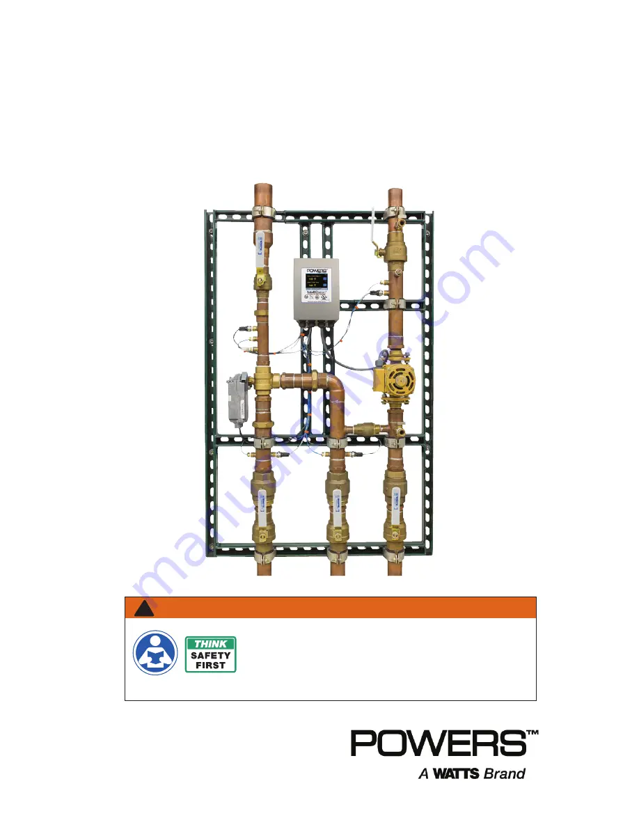
Intelli

Station

®

Digital Water Mixing
and Recirculation System

Read this Manual BEFORE using this equipment.
Failure to read and follow all safety and use information can result  

in death, serious personal injury, property damage, or damage to the  

equipment. Visit PowersControls.com with any questions. 
Keep this Manual for future reference.

WARNING

!

Summary of Contents for LFIS150

Page 1: ...System Read this Manual BEFORE using this equipment Failure to read and follow all safety and use information can result in death serious personal injury property damage or damage to the equipment Visit PowersControls com with any questions Keep this Manual for future reference WARNING ...

Page 2: ......

Page 3: ...PRODUCT OR ANY ASSOCIATED PRODUCTS COST OF REPAIR COST OF ANY SUBSTITUTE PRODUCTS OR SERVICES DELAY DAMAGES LABOR CHARGES FINES PENALTIES ECONOMIC OR NON ECONOMIC LOSSES ARISING DIRECTLY OR INDIRECTLY FROM THE SALE PURCHASE OWNERSHIP INSTALLATION OR USE OF THE PRODUCT WHETHER BASED ON BREACH OF WARRANTY BREACH OF CONTRACT NEGLIGENCE STRICT LIABILITY OR ANY OTHER LEGAL THEORY What will Powers do TH...

Page 4: ...PUTER NETWORK OR SYSTEM POWERS HAS NO RESPONSIBILITY OR LIABILITY ARISING FROM THE UNAUTHORIZED USE OF THE INTELLISTATION THE CONNECTION TO OR INTEGRATION WITH A USER S OR ANY OTHER COMPUTER NETWORK OR SYSTEM ANY HARDWARE OR SOFTWARE NOT SUPPLIED BY POWERS ANY DATA THAT IS INCORRECT CORRUPT OR CORRUPTED LOST STOLEN OR PIRATED ANY FAILURE TO SECURE THE INTELLISTATION OR THE USER S OR ANY OTHER COMP...

Page 5: ...ormation 3 Radio Frequency Warnings Hazards 3 Intellistation Description Specifications 4 Description of Controls Functions 9 Set up and Programming 20 Sanitization 31 Powers Intellistation BAS Integration Manual 37 Troubleshooting 52 Scheduled Testing Inspection and Maintenance 63 ...

Page 6: ...well as any requirements of local state and federal law Failure to do so could result in death serious personal injury property damage or damage to the equipment This Manual should be considered a permanent part of the IntelliStation and be kept available for easy reference by any user If this equipment or any of its parts becomes damaged or needs repair stop using the equipment and contact an exp...

Page 7: ...s and follow all safety and other information Learn how to properly and safely use the equipment BEFORE installing set up using or servicing Keep the Manual available for easy access and future reference Replace missing damaged or illegible Manual and product labels Replacement Manuals available at PowersControls com This pictorial alerts you to the need to read the manual This pictorial alerts yo...

Page 8: ...cteria as part of a user directed and controlled thermal eradication protocol The IntelliStation Control Module supports building automation systems BAS communication with BACnet IP BACnet MSTP and Modbus protocols allowing remote programming and data viewing Installation and adjustment of the IntelliStation are the responsibility of the owner and installer and must be done by qualified personnel ...

Page 9: ... 0 3 25 82 6 2 48 63 0 19 93 506 2 33 28 845 3 8 23 209 0 11 80 299 8 8 13 206 4 5 12 130 0 LFIS200 IS SHEET LINE ART LFIS150 LFIS200 Dimensions are shown 1 2 Dimensions in parentheses are in mm P1 T1 T4 T2 P2 T3 P4 P3 FT1 Control Unit Mixed Outlet Temp Pressure Sensors Hot Temp Pressure Sensors Electronically Actuated Valve Recirc Temp Pressure Sensors Cold Temp Pressure Sensors Recirculation Pum...

Page 10: ...ge 120 180 F 49 82 C Cold Water Inlet Temperature Range 39 80 F 4 27 C Minimum Flow 0 5 gpm 1 89 lpm Outlet Water Temperature Adjustment Range 80 180 F 27 82 C Listing Compliance ASSE1017 cUPC NSF CSA 24 UL873 BACnet Testing Laboratories BTL Ambient Temperature 32 F 0 C to 104 F 40 C Ambient Humidity 0 90 RH non condensing SUITABLE FOR INDOOR USE ONLY With Equal Pressure Minimum flow when IntelliS...

Page 11: ...ice freezing temperature direct sunlight or excessive heat Keep work area clean well lighted free of clutter and distractions and accessible only by authorized personnel and workers IntelliStation Control Module and touchscreen display must be located in accessible and well lighted area for use servicing repair or replacement by authorized personnel IntelliStation Control Module is electrically po...

Page 12: ...V P4 P3 T2 T3 P1 P2 25 23 24 22 Com Com Com Com 21 39 40 Cs T4 18 19 Gnd RS 485 20 16 17 Alert Relay L G N Recirculation Pump 115 V ac Power Supply 43 44 45 46 N N L Power Pmp Recirc Return Flow Sensor F2 Mixed Outlet Flow Sensor F1 Mixed Outlet Temperature Sensor T1 Mixed Outlet Fast Temperature Sensor Recirc Return Temperature Sensor T2 Cold Supply Temperature Sensor T3 Hot Supply Temperature Se...

Page 13: ... system and to configure the controls The following sections describe and explain the user interface to assist in navigating and configuring the control After power up the Attention screen shown below will appear You have 60 seconds to begin system navigation The Control will begin mixing operation after 60 seconds The Attention message will appear again after 10 seconds of inactivity until the 60...

Page 14: ...t Flow Flow rate measured at the mixed outlet F1 gpm or m3 h or lpm Recirc Flow Flow rate measured on the recirculation return piping F2 gpm or m3 h or lpm Valve Position Control Voltage supplied to the mixing valve V Mix Percent Mixed percent hot to total flow i e Tmixed Tcold Thot Tcold Available on models with optional flow monitoring package Field 1 Label Field 1 Select Field 2 Select Field 2 ...

Page 15: ...function icons Unlock Setup Monitor Sanitize Home and Toolbox as shown below On the Programming Menu the and icons are the only active icons until the control is unlocked See Unlock the System in the Set up and Programming section of this Manual Touching the icon takes the user back to the Home Screen Touching the icon takes the user to the Unlock function screen shown below UNLOCK SETUP MONITOR S...

Page 16: ... passcode The icon will take you back to the Programming Menu The icon will show additional information if available After entering the correct passcode the Setup Monitor Sanitize and Toolbox functions can be accessed from the Programming Menu screen The following Sections generally outline and describe these functions Touching the icon on the Programming Menu will allow access to the Setup functi...

Page 17: ... dead head protection ON Pump is always on OFF Pump is always off Pump Head 0 0 to 50 0 psi 8 5 psi If the head measured across the pump is greater than this value the pump will turn remain off since it can not generate any flow at these operating conditions Dead Head Protection Pump Min On Off Time 0 to 60 min 1 min The minimum time the pump runs or remains off Return Target 80 F to 180 F 130 F T...

Page 18: ...ttons on screen are OK DEL TAB Subnet Mask 0 0 0 1 to 255 255 255 255 255 255 255 0 IP Configuration Manual Use keypad entry 0 thru 9 key in Subnet IP Address Buttons on screen are OK DEL TAB Gateway Address 0 0 0 1 to 255 255 255 255 192 168 0 1 IP Configuration Manual Use keypad entry 0 thru 9 key in Gateway IP Address Buttons on screen are OK DEL TAB MAC Address aa bb ee ff 11 22 Unique to each...

Page 19: ...me by periodic automatic renewal requests Register Foreign Dev OFF Use keypad entry 0 thru 9 key in BBMD TIME Buttons on screen are OK DEL BBMD IP 0 0 0 1 to 255 255 255 255 127 127 127 127 BAS Type BACnet Use keypad entry 0 thru 9 BACnet Foreign device internet Protocol address A numerical label assigned to the foreign device Register Foreign Dev OFF key in IP Address Buttons on screen are OK DEL...

Page 20: ...t Inlet Low 22 to 266 F Always The lowest measured hot inlet temperature since last cleared Pressure High 0 65535 psi Always psi or kPa The highest measured DHW outlet pressure since last cleared Resolution in tenths Pressure Low 0 65535 psi Always psi or kPa The lowest measured DHW outlet pressure since last cleared Resolution in tenths Energy 0 65535 Therms or GJ Optional F1 and F2 Flow Sensors ...

Page 21: ...by the owner or manager of the water distribution system The owner or manager of the water distribution sys tem has sole responsibility to protect end users facility employees or contractors personnel performing the Sanitization and bystanders from scalding burning thermal shock or other hazards from possible exposure to water or any parts of the water distribution system during Sanitization and c...

Page 22: ...80ºF 140ºF After PIN correctly entered The sanitization target temperature Time 0 to 600 mins 60 mins After PIN correctly entered Countdown starts once DHW is up to the Sanitization Temperature Sanitization Timer Mode ON OFF OFF After PIN correctly entered Turn sanitization on or off The Sanitization Function allows access to the following fields Mode OFF Temperature 160 F Time 30 min Back Up Down...

Page 23: ...nits F C F Always Units used for temperature display Flow Units gpm m h lpm gpm Optional F1 or F2 Flow Sensors present Units used for Flow Rate display Energy Units TH GJ MBtu kWh MBtu Optional F1 and F2 Flow Sensors present Units used for calculated Energy Usage display Pressure Units psi kPa psi Always Units used for Pressure display Backlight 10 to 100 100 Always Adjust the brightness of the LC...

Page 24: ...y will show a 60 second countdown timer and read NOTICE The control will begin mixing operations automatically after 60 seconds During the 60 seconds the user may adjust setting and configure the control by touching anywhere on the screen to access the PRGM menu If the user does nothing the control will automatically route to the home screen after 60 seconds and begin normal operation 3 The Home S...

Page 25: ...o select and set your own passcode on the Home Screen touch the icon in the lower left corner as shown below 2 You will be directed to the Programming Menu which appears as shown below 3 On the Programming Menu touch the icon The Unlock function screen will appear and you will be prompted to enter the passcode NOTICE Home Screen UNLOCK SETUP MONITOR SANITIZE HOME TOOLBOX Programming Mixed Outlet S...

Page 26: ... and touch the icon again to finalize the passcode change If you make a mistake when re entering your new passcode and it does not match your first entry the icon will be deactivated If this happens press and try entering the new passcode again NOTICE To reset the passcode to the factory setting on the Programming menu press and hold the icon for 10 seconds When the passcode is reset you will be a...

Page 27: ...acceptance screen 3 You must touch the icon to proceed to the Programming Menu and to use system functions Touching the icon means you will not be able to change system settings and you accept all default settings including the outlet water temperature set point of 120 F 49 C as safe and appropriate for the water distribution system users and the facility You will be returned to the Programming sc...

Page 28: ...er or manager of the water distribution system is solely respon sible for determining the safe and appropriate temperatures to protect people using contacting or exposed to water or any parts of the water dis tribution system from scalding burning thermal shock or other hazards and to control water borne bacteria in the system Only qualified and authorized personnel who fully understand each funct...

Page 29: ...25 Set up and Programming Touch the icon which will direct you to the Setup Menu which will appear as LOCK SETUP MONITOR SANITIZE HOME TOOLBOX Programming System Network BAS Setup Back ...

Page 30: ... outlet water temperature or electing default tempera ture point of use mixing valves and or temperature limiting devices MUST be installed at all fixtures faucets sinks tubs showers etc BAS Setpoint Max 140 F Mixed Out Setpoint 140 F Pump Operation Auto Pump Min On Off Time 1 min High Temp Alert 150 F Pump Head 0 0 psi Return Target 130 F Return Differential Back Up Down System Enter 10 F ...

Page 31: ...e appropriate and desired outlet water temperature for your users application and facility by using the slider icon or by touching the right or left arrows until the selected temperature is displayed BAS Setpoint Max 140 F Mixed Out Setpoint 140 F Pump Operation Auto Pump Min On Off Time 1 min High Temp Alert 150 F Pump Head 0 0 psi Return Target 130 F Return Differential Back Up Down System Enter...

Page 32: ...et Point select ed and set make sure the Mixed Outlet Temperature is within desired operating range Home Screen The owner or manager of the water distribution system is solely responsible for determining the safe and appropriate temperatures to protect people using contacting or exposed to water or any parts of the water distribution system from scalding burning thermal shock or other hazards and ...

Page 33: ...e icon on the Programming Menu and follow the instructions under Accessing other settings on the System Setup Menu below 3 If you are done with programming and settings at this time touch the icon on the Programming Menu and you will be returned to the Home Screen 2 If you want to access other settings on the System Setup Menu touch the icon on the 3 If you are done with programming and settings a...

Page 34: ...n 10 F above setpoint Pump Operation Pump setting AUTO is temperature and pressure based pump control ON pump is always ON OFF pump is always OFF Pump Head If pressure across the pump is greater than input value pump will remain OFF Pump Min On Off Time The minimum time the pump remains on or off Return Target Designated temperature of return line water from facility Return Differential Designated...

Page 35: ...rature set point Always read and follow the User Guide Instruction Manual DANGER The Sanitization function produces high water temperatures and is intended ONLY for use as part of a user directed controlled and supervised thermal eradication protocol that has been safely and properly designed to help limit water borne bacteria within the tempered water distribution system The instructions containe...

Page 36: ...32 Sanitization 1 On the Programming Menu Touch the icon which will direct you to the responsibility and liability acceptance page LOCK SETUP MONITOR SANITIZE HOME TOOLBOX Programming ...

Page 37: ...e icon you will be directed to the Sanitization menu screen 4 Using the slide bar or directional arrows select the desired outlet water temperature Mode OFF Temperature 160 F Time 30 min Back Up Down Sanitization Enter OK Sanitization 3 Select the Sanitization temperature first by highlighting the TEMPERATURE function on the Sanitization menu and then touching During first 60 seconds upon power up...

Page 38: ...RE starting the Sanitization function make sure you are in full compliance with a safely and properly designed thermal eradication protocol protecting end users facility employees or contractors person nel performing the Sanitization and bystanders from scalding burning thermal shock or other hazards OK Sanitization Mode OFF Temperature 160 F Time 30 min Back Up Down Sanitization Enter ...

Page 39: ... the Sanitization menu and touch During first 60 seconds upon power up mode setting does not appear 8 Once in the MODE menu toggle to the ON radio button and then select OK Sanitization Mode OFF ON Mode OFF Temperature 160 F Time 30 min Back Up Down Sanitization Enter NOTICE ...

Page 40: ...te Mixed Outlet Temperature 9 After Sanitization Mode has completed user selected run time has elapsed the IntelliStation will go into a Cool Down Mode to return to the Mixed Outlet temperature prior to sanitizing Remaining 29 min 59 sec SANITIZING 160 F Mixed Outlet Temp PRGM Recirc Pump ON STOP COOLING DOWN 152 F Mixed Outlet Temp PRGM Recirc Pump ON ...

Page 41: ...ted BAS See IntelliStation User Guide Instruction Manual for additional information 1 Configure the control to communicate using the User Interface BAS Menu information within this manual and or the BAS Integration Manual 1 After completely de energizing and disconnecting all power from IntelliStation and performing required LOCK OUT TAG OUT carefully open the IntelliStation control module by rele...

Page 42: ... With the control module open the BACnet Modbus and Alert Relay connections are visible on the bot tom side of the main control board as shown below 3 The control module has a plug installed in an unused hole through the enclosure to allow for easy installation of the BAS wires Remove this plug and run the BAS wires through this hole to the control A grommet or wire protector similar to those used...

Page 43: ...not to exceed 150 ft 45 7m for CAT 5E or 300 ft 91 4 m for CAT 6 Check continuity across each wire 5 If connecting to a BACnet MSTP system run the A B Gnd terminals from the nearest BAS system component and connect to terminals 21 20 and 22 Gnd of the IntelliStation Control Module 1069 NOTICE IntelliStation and BAS connections must be properly grounded DANGER DO NOT ground to the enclosure Ground ...

Page 44: ...llistation Control Module Menu From the home screen depress the icon to access the Programming menu From within the Programming menu shown below only the and icons are active until the control is in the unlocked state Note After 60 seconds of inactivity the control automatically locks and returns to the home screen From within the Programming menu shown below only the and icons are active To unloc...

Page 45: ...ering 1017 and selecting the icon If the wrong code was entered select to try again Note the icon will only work if the correct code is entered Once unlocked the control automatically redirects to the Programming menu but this time the icon will appear as icon indicating that the control is unlocked and the other icons SETUP MONITOR SANITIZE TOOLBOX will now be active will appear as icon indicatin...

Page 46: ...Automation menu Note depending on the BAS Type selected various user configurable items will now appear within the Building Automation menu A table of the user definable items is shown on the next page The Building Automation BAS Menu shows default settings for each of the communication protocols supported by this control BACnet IP BACnet MSTP or Modbus NONE BAS Type OK Up Down BAC IP BAC MSTP MOD...

Page 47: ...wal requests Register Foreign Dev OFF Use keypad entry 0 thru 9 key in BBMD TIME Buttons on screen are OK DEL BBMD IP 0 0 0 1 to 255 255 255 255 127 127 127 127 BAS Type BACnet Use keypad entry 0 thru 9 BACnet Foreign device internet Protocol address A numerical label assigned to the foreign device Register Foreign Dev OFF key in IP Address Buttons on screen are OK DEL BBMD PORT 0 to 65535 47808 B...

Page 48: ...t is selected Press to save this setting and return to the Building Automation menu shown below with Register Foreign Dev set to ON Note the additional setting available with the Register Foreign Dev set to ON To toggle from OFF to ON press on the icon next to the ON setting to change the icon to To toggle from OFF to ON press on the icon next to the ON setting to change the icon to To toggle from...

Page 49: ...dditional information on configuring the BACnet settings see the BACnet Specifications of this document The settings available with the BAS Type are shown below Each of the settings can be adjusted by depressing the and icons to highlight the setting of interest and depressing the icon to adjust the setting BAS Type BAC IP BACnet Device ID 0000001 Register Foreign Dev ON BACnet Port 47808 BBMD Tim...

Page 50: ...t to save the setting and return to the Building To toggle from RTU to ASCII press on the icon next to the ASCII setting to change the icon to indicating that this state is what is selected Press to save this setting and return to the Building Automation menu Note for additional information on configuring the Modbus settings see the Modbus Specifications of this document To toggle from RTU to ASCI...

Page 51: ...pervised protocol that has been safely and properly designed It is recommended to install IntelliStation as part of a ASSE 1070 compliant water distribution system including point of use mixing valves Always read and follow User Guide Instruction Manual and all product warnings and labels and comply with all governmental and safety requirements BACnet Standardized Device Profile ANNEX L BACnet App...

Page 52: ...emperature R F 50 to 180 4 AI DHW Pressure The mixed outlet pressure R psi 0 to 200 5 AI DHW Recirc Pressure Recirculation Pump Inlet Pressure R psi 0 to 200 6 AI Hot Pressure Hot supply inlet pressure R psi 0 to 200 7 AI Cold Pressure Cold supply inlet pressure R psi 0 to 200 8 AI DHW Flow Mixed Outlet Flow Rate R gpm 0 to 160 9 AI Recirc Flow Recirculation Return Flow Rate R gpm 0 to 40 10 AI DH...

Page 53: ...mum Cable Length Without terminating resistors 115 000 baud 177 m 580 ft 57 600 baud 353 m 1 158 ft 19 200 baud 1 000 m 3 280 ft 9 600 baud 1 000 m 3 280 ft 2 400 baud 1 000 m 3 280 ft With 2 x 120 Ohm resistors 115 000 baud 1 000 m 3 280 ft 57 600 baud 1 000 m 3 280 ft 19 200 baud 1 000 m 3 280 ft 9 600 baud 1 000 m 3 280 ft 2 400 baud 1 000 m 3 280 ft Start Bit 1 Bit Data Length 8 Bits for RTU M...

Page 54: ...Max R F Input U16 50 to 180 F 2 DHW Temp R F Input U16 50 to 220 F 3 DHW Recirc Temp R F Input U16 50 to 220 F 4 Hot Temp R F Input U16 50 to 220 F 5 Cold Temp R F Input U16 50 to 220 F 6 DHW Pressure R psi x 10 Input U16 0 to 170 psi 7 DHW Recirc Pressure R psi x 10 Input U16 0 to 170 psi 8 Hot Pressure R psi x 10 Input U16 0 to 170 psi 9 Cold Pressure R psi x 10 Input U16 0 to 170 psi 10 Valve P...

Page 55: ...r 4 Faulty Recirc Return T2 sensor 5 Faulty Cold Supply T3 sensor 6 Faulty Hot Supply T4 sensor 7 Faulty Mixed Outlet Pressure P1 sensor 8 Faulty Recirc Return Pressure P2 sensor 9 Faulty Cold Supply Pressure P3 sensor 10 Faulty Hot Supply Pressure P4 sensor 11 Faulty Mixed Outlet Flow F1 sensor 12 Faulty Recirc Return Flow F2 sensor 13 Max Temp Exceeded ...

Page 56: ...s operation output and risks should perform this action Personnel performing Balancing Routine and the owner or manager of the water distribution system MUST take appropriate safeguards to protect people from using contacting or exposure to water or any parts of the water distribution system Always read and follow the User Guide Instruction Manual 1 The Balancing Routine is designed to give the so...

Page 57: ...e hot inlet isolation valve 4 the cold inlet isolation valve 5 and the hose connection valve 6 are in the fully open position 1 2 3 P1 T1 T4 T2 P2 T3 P4 P3 FT1 4 5 6 Control Unit Mixed Outlet Temp Pressure Sensors Hot Temp Pressure Sensors Electronically Actuated Valve Recirc Temp Pressure Sensors Cold Temp Pressure Sensors Recirculation Pump Hot Water Inlet Cold Water Inlet Return Mixed Water Out...

Page 58: ... screen check the Mixed Outlet Setpoint and the Hot Supply Temp using the icon to cycle through the fields The Hot Supply Temp needs to be above the set point or the panel will not be able to reach the set point 3 If the Hot Supply Temp is BELOW the Mixed Outlet Setpoint a Ensure flow is above the minimum rated flow by opening the hot water valve on two to four fixtures being supplied with tempere...

Page 59: ... hot water from reaching the panel and there is sufficient flow through the panel reset the control by press ing the icon to access the Programming menu Unlock the control see Unlock the System of this manual for more detail and then select the to navigate to the Toolbox menu shown below From within the Toolbox menu use the icon to highlight Reset as shown above then press This will access the Res...

Page 60: ...rt at 800 669 5430 or info PowersControls com NOTICE Always use proper precautions when accessing circuit breaker box Press the and then and the control will reset and begin a start up sequence 5 Reset the control by opening and closing the circuit breaker switch and wait 60 seconds to resume normal operation OK Toolbox Reset No Yes ...

Page 61: ... Screen check the Cold Supply Temp using the icon see below to cycle through the various fields Ensure that it is lower than the set point temperature and that the cold supply line has no obstructions or closed valves restricting flow to the IntelliStation 4 Reset the control by opening and closing the circuit breaker switch and wait 60 seconds to resume normal operation Closed OFF Open ON Always ...

Page 62: ...oper precautions when accessing circuit breaker box 6 On the Toolbox menu use the icon to highlight Reset as shown above then press This will access the Reset menu shown below 7 Press the and then and the control will reset and begin a start up sequence 8 Reset the control by opening and closing the circuit breaker switch and wait 60 seconds to resume normal operation OK Toolbox Reset No Yes No Lo...

Page 63: ... performed by certified and qualified electrician DANGER 3 Disconnect all power and fully de energize IntelliStation BEFORE opening the control module Open the Control Module and locate the non functioning sensor 4 Reset the control by pressing the icon to access the Programming menu Unlock the control see Detailed User Interface this manual and then select the to navigate to the Toolbox menu show...

Page 64: ...f this Manual for more detail 6 If problem persists after conducting the above outlined problem solving procedure contact Powers for replacement sensor s Always use proper precautions when accessing circuit breaker box Press the and then and the control will reset and begin a start up sequence Note Alternatively the control can be reset by opening and closing the circuit breaker switch and waiting...

Page 65: ...g menu The System Monitor Screen is shown below The How to Clear information presented below is also available from within the control user interface by pressing the key from within the System Monitor while viewing the Current Error For more information on navigating and using the user interface see the control module interface gpm Mixed Outlet High 109 F Energy Used 0 MBtu Hot Inlet High 158 F Mi...

Page 66: ...nsure that T3 sensor wiring is correct Continues operation 7 Faulty Hot Supply T4 sensor Ensure that T4 sensor wiring is correct Continues operation 8 Faulty Mixed Outlet Pressure P1 sensor Ensure that P1 sensor wiring is correct Continues operation 9 Faulty Recirc Return Pressure P2 sensor Ensure that P2 sensor wiring is correct Continues operation 10 Faulty Cold Supply Pressure P3 sensor Ensure ...

Page 67: ...ater conditions and or unauthor ized adjustments or repair could render the product ineffective for the service intended Regular checking and cleaning of the product s internal and external components helps assure maximum life and proper product function Replacement Part Description 81019285 1 Inch 3 way valve 81019286 2 Inch 3 way valve 81019287 Actuator 81019288 150psi Pressure sensor with wire ...

Page 68: ...ntelliStation MUST be performed by certified and qualified electrician DANGER Tools Required 10mm and 3 8 sockets elbow and torque wrench Not required if replacing both valve and actuator 3 8 wrench Not required if replacing both valve and actuator 2 5mm Allen key Not required if replacing both valve and actuator 1 8 3 2mm 2 slot screwdriver Not required for valve only replacement Wire Stripper an...

Page 69: ...e detector to confirm that the unit is NOT energized 1 Grey 2 N A 3 Pink 4 Red 5 Black Control Unit interior 3 Locate the Actuator Cable Remove the Actuator Cable from the control box and stand supports If needed snip cable ties making sure not to damage any other wires when removing the cable ties 4 Also note the routing of the actuator cable for reinstallation 5 Remove the actuator from the valv...

Page 70: ... either the shifting spanner or the gas grip loosen the three unions holding the valve in place see on next page Armature Clamping Nut Support Plate Bolts Actuator BEFORE attempting to open Control Module a certified and qualified electrician MUST fully de energize and disconnect all electrical power from IntelliStation Perform required LOCK OUT TAG OUT procedures When done reconnection and reener...

Page 71: ...nd transfer them to the replacement valve for reinstallation 6 To reinstall the valve simply reverse the above outlined procedure If installing Valve and Actuator V A combination proceed to Step 8 of actuator installation procedure once the V A have been plumbed back into the stand To install a replacement actuator the positioning of both the actuator and valve needs to be confirmed prior to insta...

Page 72: ... Marked Correct in the picture below Correct Incorrect Incorrect Actuator 3 The valve must be positioned such that it is fully opened to the branch cold supply The Correct and Incorrect positions are shown below These images are looking in the outlet port of the valve note the black plastic flow linearization insert Manual Override Button Actuator When positioned correctly the valve outlet plastic...

Page 73: ...been aligned correctly the actuator can be reinstalled onto the valve by sliding actuator over the valve stem until the actuator sits tight against the actuator support plate with the actuator positioned vertically as shown below The valve outlet with plastic insert should be facing upwards NOTICE Correct Incorrect Valve Actuator ...

Page 74: ...pport plate and the actuator This play will allow the actuator to find the proper position when the armature clamping nut is tightened down Armature Clamping Nut Support Plate Bolts NOTICE 6 Tighten down the armature clamping nut using the 10mm socket and torque wrench to 50 in lbs 5 65 N m 7 Using the 3 8 socket elbow and torque wrench torque down the support plate nut to 50 in lbs Take caution n...

Page 75: ... terminal blocks as follows 1 0 10 Act Grey 2 Com N A 3 Mtr FB Pink 4 R Red 5 C Black The Com terminal of the control is not wired orange actuator wire is not used by this control 11 Utilize cable ties to secure the wires and close the control module Once the box is closed re energize the unit 12 Resume normal operation and observe that the actuator and valve are now working properly 1 Grey 2 N A ...

Page 76: ... IntelliStation 1902 EDP 2915182 2019 Powers USA Tel 800 669 5430 Fax 847 229 0526 PowersControls com Canada Tel 905 332 4090 Fax 905 332 7068 PowersControls ca Latin America 52 81 1001 8600 PowersControls com ...

Reviews: