IOM-WQ-LCTA-100_150
Installation, Operation and Maintenance
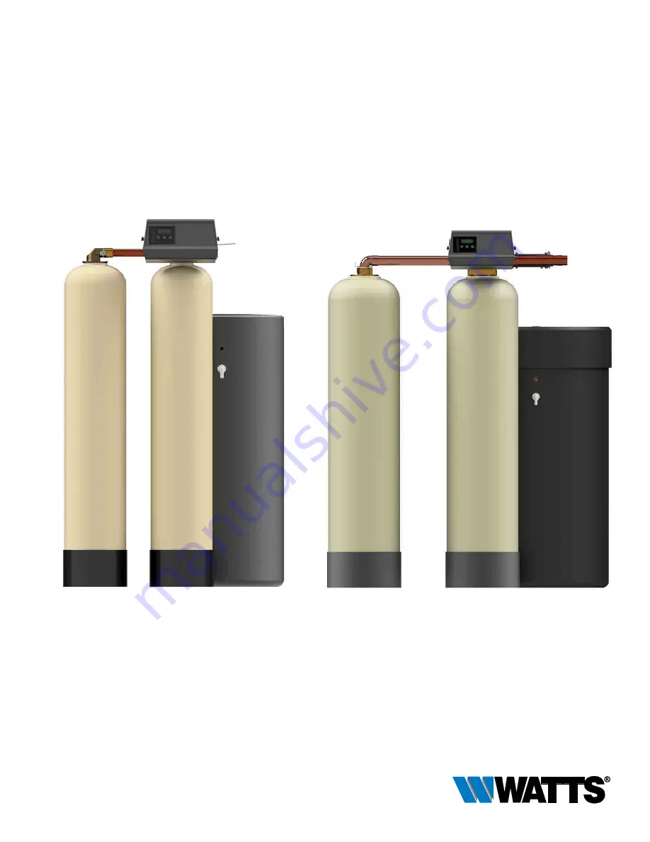
1" & 11/2" Commercial Water Softeners
Series: LCTA-100 & LCTA-150
LCTA-100 Twin Alternating Systems
LCTA-150 Twin Alternating Systems
Page 1: ...IOM WQ LCTA 100_150 Installation Operation and Maintenance 1 11 2 Commercial Water Softeners Series LCTA 100 LCTA 150 LCTA 100 Twin Alternating Systems LCTA 150 Twin Alternating Systems ...
Page 2: ...uality components Simple programming corrosion resistant mineral tank s and an easy to service design ensures this system will be durable and easy to maintain Thank You The Watts Team Softened water provides a wide variety of benefits such as reducing the potential of lime scale formation in boilers water heaters and heat exchangers to protecting the remainder of the plumbing system from costly ma...
Page 3: ...erheating of electronics may occur and ultraviolet rays from the sun may cause damage Operating ambient temperature 34 to 120 F 1 to 52 C Operating water pressure range 25 to 125psi 171 kPa to 8 6 bar All plumbing connections to the system should be made using industry accepted best practices Plumbing tape or paste may be used on metal inlet and outlet plumbing connections Do not use paste type pi...
Page 4: ...sin is used to effectively exchange calcium and magnesium hardness cations for sodium cations in the water New or freshly regenerated ion exchange resin is saturated with sodium cations As calcium and magnesium hardness cations come in contact with the ion exchange resin they attach to the resin and sodium cations are released into the water This is pos sible because the hardness cation are more a...
Page 5: ...eneration B System 7 2 Mineral Tanks 1 Meter Immediate Regeneration C System 14 2 8 Mineral Tanks 2 8 Meters Immediate Regeneration Progressive Flow Tank Staging GPM Threshold for Progressive Feature ________________________________________________ D _____________________________Other System Description 3 Controller Program Settings A Backwash ____________________________________ Minutes B Brine a...
Page 6: ...61 8 1425 561 8 1425 611 8 1552 121 2 318 277 8 708 18 457 40 1016 290 132 M2060B SE 541 2 1384 541 2 1384 591 2 1511 131 2 343 291 2 749 18 457 40 1016 350 159 M2066B SE 673 8 1711 673 8 1711 721 4 1835 145 8 371 311 2 800 18 457 40 1016 500 227 M2069B SE 665 8 1692 665 8 1692 715 8 1819 161 8 409 331 8 841 18 457 40 1016 650 295 Series LCTA 150 MODEL NO DIMENSIONS WEIGHTS A B C D E F G in mm in ...
Page 7: ...2235SE 24 x 72 10 0 100 100 lbs 30 x 50 1200 300 K 200 K 150 60 40 55 15 25 15 0 MODEL NO ORDERING CODES DESCRIPTION PIPE SIZE SPACE REQUIRED D X W X H WEIGHT LBS KGS M2058 SE 68105184 1 Cubic Foot Twin Alt Water Softener with Flow Meter 3 4 18 x 51 x 70 230 105 M2059 SE 68105193 1 5 Cubic Foot Twin Alt Water Softener with Flow Meter 3 4 18 x 51 x 76 290 132 M2060 SE 68105202 2 Cubic Foot Twin Alt...
Page 8: ...eached contact Watts customer service at 800 659 8400 Drain line flow controller for LCTA 100 Series is factory installed in valve s drain port Drain line flow controller for LCTA 150 may come loose or assembled on control valve s drain port depending on system size Verify drain line flow controller is present before proceeding See installation Diagrams page 12 13 Drain and Brine Connection Detail...
Page 9: ... during the loading of the media 4e Remove the funnel from the top of the tanks and plastic caps and tape from the top of the distributor tubes DO NOT PULL UP ON THE DISTRIBUTOR TUBES when removing the caps The distributor tube tops must remain flush with the top of the tank 4f Clean any media from the threads and top of the mineral tanks Media in the threads and on the O ring sealing sur face of ...
Page 10: ...low arrow on the drain line flow controller must point towards the drain receptacle Only plumbing tape is allowed on the drain line flow controller fitting threads WARNING Operating a system without a drain line flow controller will cause all media to flow out of the system through the drain line 15 Construct the drain line routing it to an appropriate drain recep tacle abiding buy all local build...
Page 11: ...the backwash position then unplug the system Once water flow at the drain line is observed fully open the inlet valve and allow water to flow to drain for 15 minutes to flush the resin bed of any color If water at the drain shows any discoloration continue to flush the resin bed until water at the drain is clear During this flush water is flowing through both tanks so a separate flush for the seco...
Page 12: ... proper drain connection follow all national state and local codes Do not construct drain line to elevations that exceed 4 feet above the control valve s drain port 11 The full weight of the piping and valves must be supported by pipe hangers or other means 12 Inlet and outlet headers need to be sized according to flow rate requirements by others 13 Power requirements 115v 60hz 2 7 Amps per contro...
Page 13: ... 15 Use factory supplied brine tubing Do not use smaller diameter tubing than what is supplied 16 Limit inlet pressure to not exceed maximum published operating pressure Installation Reference Notes For All System Installation Drawings Front View Side View Top View Drain water out to drain Drain and Brine Connection Detail Control Valve Brine Connection Port Connect brine tube from brine tank Use ...
Page 14: ...14 Wiring Diagram SXT 9000 9500 42743 Rev A ...
Page 15: ...he display will flash The parameter display will identify the destination cycle step BW BF RR etc and the data display will read Once the valve reaches the cycle step the display will stop flashing and the data display will change to the time remaining During regeneration the user can force the control to advance to the next cycle step immediately by pressing the extra cycle button Setting the Tim...
Page 16: ...control only enters the Program Mode with the valve in ser vice While in the Program Mode the control continues to oper ate normally monitoring water usage and keeping all displays up to date Control programming is stored in memory permanently eliminating the need for battery backup power Manually Initiating a Regeneration To occur that day at the next scheduled regeneration time 1 Press the Extra...
Page 17: ...BF Regen Cycle Step Times The time duration for each regeneration step Adjustable from OFF and 0 199 minutes NOTE If Othr is chosen under Valve Type then R1 R2 R3 etc will be displayed instead D1 D2 D3 D4 D5 D6 D7 Day of Week Settings Regeneration setting On or OFF for each day of the week on day of week systems CD Current Day The current day of the week FM Flow Meter Type All LC 100 systems use a...
Page 18: ...the Extra Cycle button while powering up the unit This resets all of the parameters in the unit Check and verify the choices selected in Master Programming Mode 1 Display Format Display Code DF This is the first screen that appears when entering Master Programming Mode The Display Format setting specifies the unit of measure that will be used for volume and how the control will display the Time of...
Page 19: ...r by V if volume capacity for a filter The Unit Capacity parameter is only available if the control type has been set to one of the metered options Use the Up and Down buttons to adjust the value as needed Range 1 999 9 x 1000 grains gallon mg liter Figure 8 7 Feed Water Hardness Display Code H Press the Extra Cycle button Use this display to set the Feed Water Hardness Enter the feed water hardne...
Page 20: ...generation the reserve will change based on the old reserve capacity and the previous day s water usage This option setting is identified by CR in the upper left corner of the screen 12 Day Override Display Code DO Press the Extra Cycle button Use this display to set the Day Override This setting specifies the maximum number of days between regeneration cycles If the system is set to a timertype c...
Page 21: ...ing and move to the next day Note that the control requires at least one day to be set to ON If all 7 days are set to Off the unit will return to Day 1 until one or more days are set to ON Figure 17 16 Current Day Display Code CD Press the Extra Cycle button Use this display to set the current day on systems that have been configured as Day of Week controls This setting is identified by CD in the ...
Page 22: ...e used at a time Figure 21 Figure 22 ST Range 0 to total number of cycles minus 1 Figure 23 ET Range Start time to total of all cycles Figure 24 Figure 25 VO Range 1 to Total Gallon Capacity Figure 26 TO Range 1 to 7200 minutes 20 End of Master Programming Mode Press the Extra Cycle button to save all settings and exit Master Programming Mode For time based set the desired Start Time ST and End Ti...
Page 23: ...r used by the unit since last installation or last reset SV Software Version Displays the software version installed on the controller NOTE Some items may not be shown depending on control configuration The control will discard any changes and exit the Diagnostics View if a button is not pressed for 60 seconds Figure 27 Figure 28 Figure 29 Diagnostics View Steps 1 Press the Up and Extra Cycle butt...
Page 24: ...identified by RC in the upper left corner of the screen Figure 30 Figure 32 Figure 33 SXT Diagnostics Cont d Figure 31 7 Press the Up button Use this display to view the Total Volume data This option is identified by TV in the upper left corner of the screen 8 Press the Up button Use this display to view the Software Version This option setting is identified by SV in the upper left corner of the s...
Page 25: ...of 3 4 sch 40 PVC that is the same height as the mineral tank and a length of 1 clear braided poly vinyl hose The hose must be long enough to reach the nearest floor drain Both of these can be acquired at a local hardware store 13 Insert one end of the pipe inside the hose and the other end of the pipe into the top of the mineral tank and down into the resin media Put the other end of the hose ins...
Page 26: ...y discolor ation continue to flush the resin bed until water at the drain is clear During this flush water is flowing through both tanks so a separate flush for the second tank is not necessary 25 Then plug the system into the power outlet and advance the system to the stand by position as shown on the position indicator 26 Fully open inlet valve For LCTA 150 series systems open outlet valve and c...
Page 27: ... TOP 7 2 68100934 C9092 FIBERGLASS MINERAL TANK 10X54 ALMOND W 2 5 8 TOP 7 2 68100967 C9094X FIBERGLASS MINERAL TANK 12X52 ALMOND W 2 5 8 TOP 7 2 68100997 C9098 FIBERGLASS MINERAL TANK 14X65 ALMOND W 4 8 TOP 7 2 68101000 C9099 4 FIBERGLASS MINERAL TANK 16X65 ALMOND W 4 8 TOP 8 68100326 A4000 SOFTENING RESIN MEDIA WATTS BRAND HIGH CAPACITY SAC NA FORM 1 CUFT BAG 9 68100354 A7005A MEDIA GRAVEL 20 FL...
Page 28: ...8108488 V2003 A MCH 02 PVC DRAIN FLOW CONTROL PVC 1 HOUSING F 12 20 GPM BUTTONS 2 1 68108568 V7102 3 5 FC BUTTON 3 5 GPM F 12 SOFTENER 2 1 68108569 V7103 05 FC BUTTON 5 0 GPM F 14 SOFTENER 2 1 68108571 V7103 07 FC BUTTON 7 0 GPM F 16 SOFTENER 2 1 68108574 V7103 10 FC BUTTON 10 0 GPM F 18 SOFTENER 2 1 68108575 V7103 12 FC BUTTON 12 0 GPM F 21 SOFTENER 2 1 68108576 V7103 15 FC BUTTON 15 0 GPM F 24 S...
Page 29: ... 68102491 G2002B BRINE TANK 18X40 BLK EMPTY 11 1 68102494 G2003 BRINE TANK 24X41 BLK EMPTY 11 1 68102500 G2004 BRINE TANK 24X50 BLK EMPTY 11 1 68102511 G2009 BRINE TANK 30X50 BLK EMPTY 12 1 68102634 H7007 BRINE SAFETY FLOAT BRINE VALVE AND AIR CHECK ASSY 2310 FOR 3 8 BRINE HOSE 12 1 68110335 K4560009 KIT AIR CHECK 900 FITTING FOR 1 2 BRINE HOSE 13 1 68102591 H1016 BRINE WELL CAP 4 13 1 68102592 H1...
Page 30: ...EAD ITEM NO QTY ORDERING CODE DESCRIPTION 1 1 68104775 K4562103 76 9000 POWERHEAD ASSEMBLY F 9000 9500 SXT W SXT CONTROLLER NO COVER OR TRANSFORMER 2 1 68104394 K4519674 TRANSFORMER 120V 24V USA 9 6VA 3 1 68104578 K4560232 112 COVER WITH LEFT WINDOW F 9000 9500 2 3 1 ...
Page 31: ...31 Replacement Parts SXT Controller Assembly SXT CONTROLLER ASSEMBLY ITEM NO QTY ORDERING CODE DESCRIPTION 1 1 68104456 K4542777 SXT CONTROLLER F 9000 9500 1 ...
Page 32: ...00 9100 W 5 GPM BLFC 1 5 GPM DLFC 9 1 68104595 K4560350 BRINE VALVE ASSEMBLY 9000 10 1 68104484 K4560022 100 BRINE FLOW CONTROL ASSEMBLY 1 00 GPM 3 8 F 9000 10 1 68104485 K4560022 25 BRINE FLOW CONTROL ASSEMBLY 0 25 GPM 3 8 F 9000 10 1 68104486 K4560022 50 BRINE FLOW CONTROL ASSEMBLY 0 50 GPM 3 8 F 9000 11 1 68104079 K4510913 00 INJECTOR NOZZLE 00 VIOLET 11 1 68104080 K4510913 000 INJECTOR NOZZLE ...
Page 33: ...4512085 FLOW CONTROL WASHER 1 2 GPM F 6 TANK 13 1 68104110 K4512086 FLOW CONTROL WASHER 1 5 GPM F 8 TANK 13 1 68104111 K4512087 FLOW CONTROL WASHER 2 0 GPM F 9 TANK 13 1 68104112 K4512088 FLOW CONTROL WASHER 2 4 GPM F 10 TANK 13 1 68104114 K4512090 FLOW CONTROL WASHER 3 5 GPM F 12 TANK 13 1 68104115 K4512091 FLOW CONTROL WASHER 4 0 GPM F 13 TANK 13 1 68104116 K4512092 FLOW CONTROL WASHER 5 0 GPM F...
Page 34: ...T F UPPER 9500 NATURAL 3 1 68104544 K4560108 PISTON ASSEMBLY F UPPER 9500 4 1 68104565 K4560133 01 SEAL SPACER KIT F LOWER 9500 5 1 68104545 K4560109 PISTON ASSEMBLY F LOWER 9500 6 1 68104172 K4513577 ORING 226 F 2900S 9500 2850 DISTRIBUTOR PILOT 7 1 68104315 K4516455 ORING 347 F 9500 TANK TO VALVE 8 1 68104614 K4560381 INJECTOR ASSEMBLY 1700 NO INJECTOR 8 1 68104615 K4560381 03 INJECTOR ASSEMBLY ...
Page 35: ...4510914 BL INJECTOR THROAT 2 BLUE 11 1 68104089 K4510914 G INJECTOR THROAT 4 GREEN 11 1 68104090 K4510914 R INJECTOR THROAT 0 RED 11 1 68104091 K4510914 W INJECTOR THROAT 1 WHITE 11 1 68104092 K4510914 Y INJECTOR THROAT 3 YELLOW 12 1 68104209 K4514801 3CY INJECTOR NOZZLE 3C YELLOW 12 1 68104210 K4514801 4CG INJECTOR NOZZLE 4C GREEN 12 1 68104211 K4514801 5CW INJECTOR NOZZLE 5C WHITE 12 1 68104212 ...
Page 36: ...12 INTERCONNECTING TUBE ASSEMBLY TO 2ND TANK F 9000 W 8 5 TUBES F 12 TANKS 2 1 68104288 K4515823 14 INTERCONNECTING TUBE ASSEMBLY TO 2ND TANK F 9000 W 10 5 TUBES F 14 TANKS 2 1 68104289 K4515823 16 INTERCONNECTING TUBE ASSEMBLY TO 2ND TANK F 9000 W 12 5 TUBES F 16 TANKS 3 1 68104232 K4515078 01 ADAPTER COUPLING 1 W O RINGS 4 1 68104150 K4513255 MOUNTING CLIP 5 1 68104617 K4514202 SCREW 8 32 X 0 37...
Page 37: ... 1 1 68104705 K4560715 16 INTERCONNECTING TUBE ASSEMBLY TO 2ND TANK F 9500 F 14 16 TANKS 1 1 68104706 K4560715 20 INTERCONNECTING TUBE ASSEMBLY TO 2ND TANK F 9500 F 18 20 TANKS 1 1 68104707 K4560715 24 INTERCONNECTING TUBE ASSEMBLY TO 2ND TANK F 9500 F 20 24 TANKS 2 1 68104336 K4516916 ADAPTER WITH O RINGS F SECOND TANK F 9500 ...
Page 38: ...00 NO FLOW CONTROLLER 1 1 68104503 K4560037 630 BRINE VALVE ASSEMBLY 1600 F 9500 W 1 0 GPM FLOW CONTROLLER 2 1 68104340 K4516960 BRINE TUBE 1600 F 9500 3 1 68104482 K4560020 25 BRINE FLOW CONTROL ASSEMBLY 25 GPM F 1600 3600 3 1 68104483 K4560020 50 BRINE FLOW CONTROL ASSEMBLY 50 GPM F 1600 3600 3 1 68104481 K4560020 100 BRINE FLOW CONTROL ASSEMBLY 1 0 GPM F 1600 3600 1 2 3 ...
Page 39: ...LOW CONTROLLER 2 1 68104339 K4516959 BRINE TUBE 1700 F 9500 3 1 68104109 K4512085 FLOW CONTROL WASHER 1 2 GPM 3 1 68104110 K4512086 FLOW CONTROL WASHER 1 5 GPM 3 1 68104111 K4512087 FLOW CONTROL WASHER 2 0 GPM 3 1 68104112 K4512088 FLOW CONTROL WASHER 2 4 GPM 3 1 68104113 K4512089 FLOW CONTROL WASHER 3 0 GPM 3 1 68104114 K4512090 FLOW CONTROL WASHER 3 5 GPM 3 1 68104115 K4512091 FLOW CONTROL WASHE...
Page 40: ...516959 BRINE TUBE 1700 F 9500 3 1 68104109 K4512085 FLOW CONTROL WASHER 1 2 GPM 3 1 68104110 K4512086 FLOW CONTROL WASHER 1 5 GPM 3 1 68104111 K4512087 FLOW CONTROL WASHER 2 0 GPM 3 1 68104112 K4512088 FLOW CONTROL WASHER 2 4 GPM 3 1 68104113 K4512089 FLOW CONTROL WASHER 3 0 GPM 3 1 68104114 K4512090 FLOW CONTROL WASHER 3 5 GPM 3 1 68104115 K4512091 FLOW CONTROL WASHER 4 0 GPM 3 1 68104116 K451209...
Page 41: ...t Parts 3 4 Plastic Electronic Turbine Meter Assembly 3 4 PLASTIC ELECTRONIC TURBINE METER ASSEMBLY ITEM NO QTY ORDERING CODE DESCRIPTION 1 1 68104664 K4560626 METER ASSEMBLY 3 4 ELECTRONIC TURBINE W CLIPS SCREWS 1 ...
Page 42: ...onic Turbine Meter Assembly 11 2 INCH PLASTIC ELECTRONIC TURBINE METER ASSEMBLY ITEM NO QTY ORDERING CODE DESCRIPTION 1 1 68104737 K4561560 13 METER ASSEMBLY 11 2 PLASTIC ELECTRONIC 2 2 68110410 K4541597 PLUMBING ADAPTOR BRASS 11 2 MNPT 2 1 2 ...
Page 43: ...sembly Stainless Steel For 9000 BYPASS VALVE ASSEMBLY STAINLESS STEEL FOR 9000 ITEM NO QTY ORDERING CODES DESCRIPTION 1 1 68104507 K4560040SS BYPASS VALVE ASSEMBLY 3 4 STAINLESS 1 1 68104508 K4560041SS BYPASS VALVE ASSEMBLY 1 STAINLESS 1 ...
Page 44: ...egeneration Inlet of control plugged due to foreign material broken loose from pipes by recent work done on plumbing system Remove piston and clean control valve Loss of mineral through drain line Air in water system Assure that well system has proper air eliminator control Check for dry well condition Improperly sized drain line flow control Check for proper drain rate Iron in conditioned water F...
Page 45: ...verify that it functions correctly If the error re occurs unplug the unit and contact technical support 2 Regen Failure The system has not regenerated for more than 99 days or 7 days if the Control Type has been set to Day of Week Perform a Manual Regeneration to reset the error code If the system is metered verify that it is measuring flow by running service water and watching for the flow indica...
Page 46: ...46 Water Softener Flow Diagrams 2 Backwash Position 1 In Service Position 3 Tanks Switching Position Meter Initiated Regeneration 4 Brine Draw Position 5 Slow Rinse ...
Page 47: ...47 7 Brine Tank Fill Position 6 Rapid Rinse Position 8 In Service Position Tanks Switched Water Softener Flow Diagrams ...
Page 48: ...48 Flow Data and Injector Draw Rates Down Flow 9000 9500 Injector Flow Data 1600 Series Injectors ...
Page 49: ...49 Flow Data and Injector Draw Rates Down Flow 9500 Injector Flow Data 1600 1700 Series Injectors ...
Page 50: ...00 Brine System Standard Size Color 0 Red 1 White 2 Blue 3 Yellow 4 Green Injector Nozzle and Throat Chart for 1600 1700 Brine Systems 1700 Brine System Standard Size Color 3C Yellow 4C Green 5C White 6C Red ...
Page 51: ..._________________________________________________________________________________________________________ ________________________________________________________________________________________________________________________________________ ________________________________________________________________________________________________________________________________________ ____________________...
Page 52: ...in the warranty period the Company will at its option replace or recondition the product without charge Disclaimer of Warranty THE WARRANTY SET FORTH HEREIN IS GIVEN EXPRESSLY AND IS THE ONLY WARRANTY GIVEN BY THE COMPANY WITH RESPECT TO THE PRODUCT THE COMPANY MAKES NO OTHER WARRANTIES EXPRESS OR IMPLIED THE COMPANY HEREBY SPECIFICALLY DISCLAIMS ALL OTHER WARRANTIES EXPRESS OR IMPLIED INCLUDING B...