5
EN
ENGLISH
HKF20-IM-DE-W-UK-11-2020-Rev.0.1 | Part no. 10084531
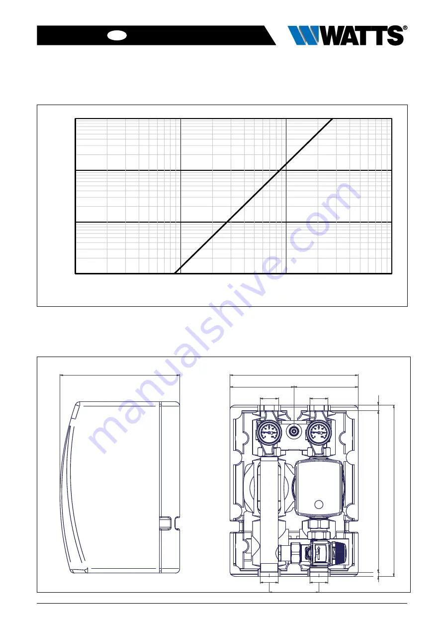
5 Overall dimensions
232
116
G1"
7
2
9
3
1
0
)
(3
90
217
4 Pressure loss curve
10
100
1.000
10.000
Flow rate [l/h]
Pr
essur
e loss [mbar]
Page 1: ...Series HKF20 Pump mixing valve group with thermostatic fix point control for heating systems Installation and Operating Manual translated from the original operating manual WattsWater eu ...
Page 2: ...the Machinery Directive 2006 42 EC has been issued for this pump group product 1 3 Product features stable mounting bracket including mounting hardware patented 3 piece EPP insulating shell all connections to the system with 1 male thread and flat sealing compact space saving design Contents 1 General information 2 1 1 Important information 2 1 2 Product conformity 2 1 3 Product features 2 2 Safet...
Page 3: ...ump group is not intended to be operated by people including children with physical sensory or mental disabilities nor by people with insufficient experience or previous knowledge 2 4 Foreseeable misuse The following is considered to be foreseeable misuse operating the pump group contrary to the specifications improper use of the pump group modifications to the pump group that were not agreed with...
Page 4: ...ctrical connection Power supply See separate pump documentation Dimensions Width x height x depth with EPP shell 240x310x217 mm Axis center distance 90 mm Sealing surfaces distance 293 mm Connections to pipe network 1 AG male thread flat sealing 55 Nm Tightening torques for screwed connections 3 4 35 Nm 1 55 Nm Material Fittings brass CW617N Pipes stainless steel Ø33 mm Plastics impact resistant a...
Page 5: ...LISH HKF20 IM DE W UK 11 2020 Rev 0 1 Part no 10084531 5 Overall dimensions 232 116 116 G1 G1 7 293 10 0 31 G1 G1 90 217 4 Pressure loss curve 1 10 100 1 000 10 100 1 000 10 000 Flow rate l h Pressure loss mbar ...
Page 6: ...m electric shock Work on parts carrying live voltage must only be carried out by trained electricians Disconnect the power supply of the system and secure it against being switched back on before carrying out any installation mainte nance cleaning or repair work The installation and commissioning of the pump group must only be carried out by trained personnel who have been authorized by the manufa...
Page 7: ...supply and return lines and check that all screw connections are tight 50 7 3 Initial Commissioning Requirement The pump group is completely assembled Connection of the power supply 1 Connect the power supply see separate pump documentation 9 The pump group switches on automatically after being connected to the power supply 2 Vent the heating system The pump group must be switched off during the v...
Page 8: ...he pump connection at the bottom and turn the pump including ball valve through 180 degrees Loosen the nut on the pipe ball valve and turn the ball valve through 180 degrees 5 Turn the pump group 180 degrees The supply line is now on the left side 6 Tighten the loosened connections to the pump and ball valve observe tightening torques Slide the pump group onto the wall bracket and fasten the retai...
Page 9: ...s and retighten sealing connec tions or replace seals as required 2 Functional checks Check that settings and operating and performance parameters are set correctly Check flow noise during operation Ask users if there are any noticeable problems 3 Ball taps Check that stop valves and ball taps can move freely 4 Pump Pay attention to the noise of the pump 5 Thermostatic mixing valve Check the therm...
Page 10: ...ing from hot water Allow the pump group to cool before servicing Do not reach into the hot medium when emptying 8 4 Installation of the circulation pump 1 Replace damaged or defective seals if necessary 2 Insert the circulation pump and tighten the nuts X fig 2 for tightening torques see Technical data on page 4 3 Connect the wiring of the circulation pump 4 Slowly open the ball valves by turning ...
Page 11: ...antle the thermostatic mixing valve with temperature setting D fig 3 by loosening the union nuts X fig 3 8 6 Installation of the thermostatic mixing valve 1 Replace damaged or defective seals if necessary 2 Insert the thermostatic mixing valve D fig 3 and tighten the nuts X fig 3 for tightening torques see Technical data on page 4 3 Slowly open the ball valves by turning the thermometer handle B f...
Page 12: ...mble the pump group or commission a specialist company with this task 3 Sort the subassemblies and component parts into recyclable materials and operating materials 4 Dispose of the subassemblies and components according to regional laws and regulations or take them to be recycled 9 1 Return shipment to the manufacturer Get in contact with the manufacturer if you would like to return the pump grou...