4
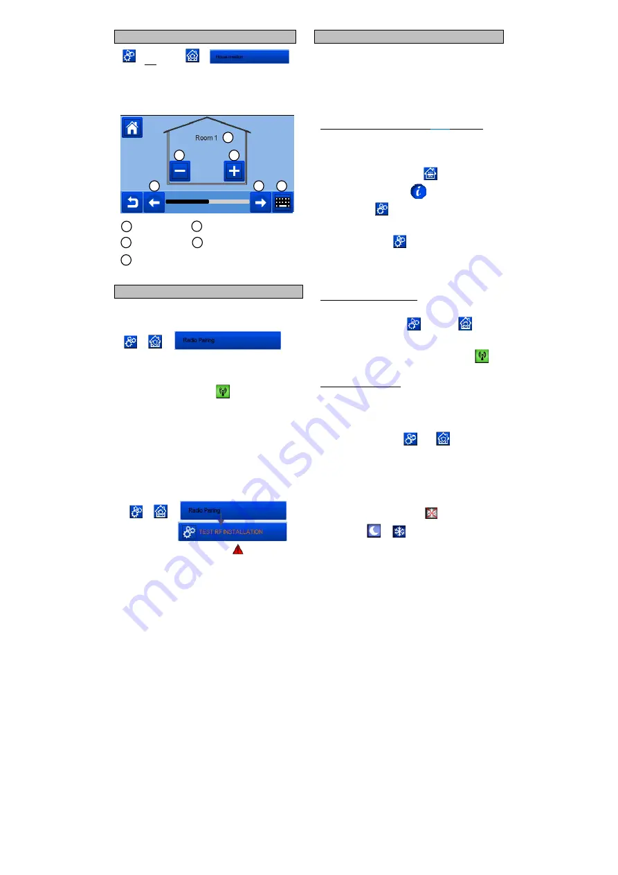
3 CREATE YOUR HOUSE
long press on
You now need to “create” your house - a list of rooms where the
various devices such as thermostats will be placed.
Create all the rooms
and re-name them eg room 1 = Kitchen,
room 2 = Lounge etc
Scroll over rooms.
To create or add a room (zone).
Current room name
To change current room (zone)
name.
To delete a room
(zone).
4 PAIR YOUR DEVICES TO CENTRAL
Install your devices
Create the room if it doesn’t exist
(See section 3)
Go to
Radio pairing
-
Choose the device type (heating
, On/Off Device etc)
- Choose the room
Note: The master must be the first paired device.
- Put the device in pairing mode (refer to device leaflet)
Start the pairing on the Central
- Follow the instructions given by the Central (check on the
device that the pairing is successful, refer to the device
leaflet)
- n.b: Automatic pairing time in case of RF communication
loss: 10s.
- When you have finished pairing all devices and installed all
devices in their final location, please check that the range
allows good communication between devices. To do this,
adjust the setpoint temperature on the central and make sure
that the information is received by the thermostat and the
receiver.
Check the successful installation
-
- You will have warning in home menu
for rf errors
communications. These errors should
disappear
in 10
minutes maximum. If not, check devices
showing
rf errors
, try
moving them to another place
and repeat the procedure.
HYDRAULIC SYSTEM PAIRING
If your installation has a number of hydraulic circuits containing
multiple pumps, you may want to drive each pump separately
from specific thermostat(s) or thermostatic actuator(s). With
smartvision you can create and control up to 4 hydraulic
circuits. Each of the circuits will have an RF remote receiver
linked to it that will activate the intended pump and boiler. If at
least one thermostat or thermostatic actuator on the circuit has
a demand, the linked receiver will operate and activate the
pump (and / or boiler).
First step: define on which circuit an
device
belongs to
With the plan of your installation, define which
devices
(excluding the receiver)
are on “circuit 1”. Then, using the
Central controller,
pair and configure all these devices on circuit
1.
To do this, in the main screen press
, enter a zone
(room)
that is on circuit 1, then press
and select one device of
circuit 1 and press
5 seconds. Now you have entered the
configuration menu of the device. Choose menu “HC”, now
you have two
options,
Electrical or Hydraulic, select Hyraulic
and then press on button
.
You can now
select the circuit,
that the device will act on,
eg circuit 1.
Proceed like this for every heating/cooling device of this circuit.
Once all elements of circuit 1 are set, do the same for the other
hydraulic circuits.
Second step: control the circuits
For each circuit, you can link a
receiver
to drive the pump/boiler
of the circuit. This can be done for example by BT-WR02 RF.
From the main screen, press
then press
. On the
list box, choose “Radio pairing”, then “Circuit”. Select the
number of the circuit, eg circuit 1. Put the element to link (BT
WR02 RF) in link mode, then start process by pressing
.
Do the same for the other circuit, if you have more.
Heat and Cool installations
If your installation includes a cooling function, you can
switch
either from Heat to Cool manually or automatically:
- If you have a BT HCM02 RF in your installation set as
“Master” (refer to Manual instruction of the device) then all
is automatic you don’t have to do anything
- For all other cases, you have to do the switch manually:
from main screen press
then
and go in
“H&C”. There you will have the choice netween “Heating
Only” “Cooling Only” or “Manual Reversible”. With this last
option, you create a shortcut in the main menu (icon 4)
where you can easily change Heat/Cool mode.
Notes:
-
In Cooling Mode, Reduced mode and Antifreeze
mode are inactive: icon
is displayed instead
of
or
.
- In the thermostat, user can configure the parameter “Cold”
that allows the zone to do Cooling or not. If it is set to “No”,
then if the mode of the zone is Cooling then the zone
won’t make Cooling.
1
1
2
3
4
5
1
2
3
4
5


