


2
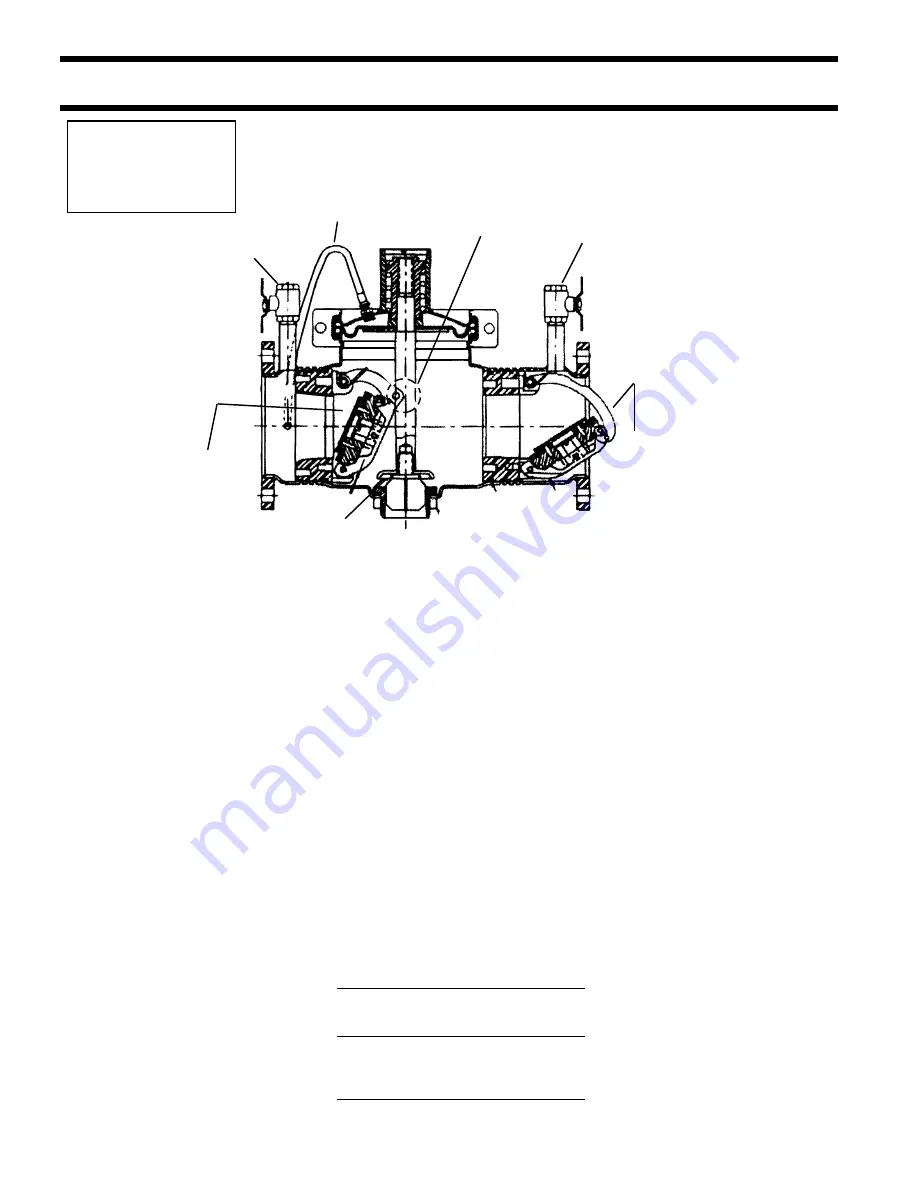
Figure 1
Valve Size Typical Flow Rates
Drain
(inches)
as sized by floor
Size
drain manufacturers
2
1
⁄
2
55 gpm
2
3
112 gpm
3
4
170 gpm
4
6 - 8 - 10
350 gpm
5
Basic Installation Instructions
Installation Note:
The flange gasket bolts for the
gate valves should be retight-
ened during installation as the
bolts may have loosened due to
storage and shipping.
Watts Series 995 Reduced Pressure Zone
Backflow Preventer
1. Backflow preventers must be installed in high-visibility locations
in order to allow for immediate notice of telltale discharge or
other malfunction. This location should also facilitate testing and
servicing and protect against freezing and vandalism.
2. Installation procedures must comply with all state and local
codes.
3. Installing a backflow preventer in a pit or vault is not recom-
mended. An air gap below the relief port must be maintained so
as to avoid flooding and submersion of the assembly, which may
lead to a cross connection. Watts recommends installations in-
doors or above ground in an insulated enclosure. (Send for ES-WB)
4. A strainer should be installed ahead of the backflow preventer to
protect the discs from unnecessary fouling.
CAUTION: Do not install a strainer ahead of the backflow preven-
ter on seldom-used, emergency water lines (i.e. fire sprinkler
lines). The strainer mesh could potentially become clogged with
debris present in the water and cause water blockage during an
emergency.
5. Normal discharge and nuisance spitting are accommodated by
the use of a Watts air gap fitting and a fabricated indirect waste
line. Floor drains of the same size MUST be provided in case of
excessive discharge.
6. When a Series 995 backflow preventer is installed for dead-end
service applications, discharge from the relief vent may occur due
to water supply pressure fluctuation during static no-flow condi-
tions. A spring load soft-seated check valve may be required ahead
of the backflow preventer.
7. ASSEMBLY: If the backflow preventer is disassembled during in-
stallation, it MUST be reassembled in its proper order. The gate
valve with the test cock is to mounted on the inlet side of the back-
flow preventer. The test cock must be on the inlet side of the
wedge. Failure to reassemble correctly will result in possible water
damage due to excessive discharge from the relief port/vent and
possible malfunction of the backflow preventer.
8. Prior to installation, thoroughly flush pipe line to remove any for-
eign matter.
9. START UP at Initial Installations and After Servicing: The down-
stream shutoff should be closed. Slowly open upstream shutoff
and allow the backflow preventer to fill slowly. Bleed air at each
test cock. When backflow preventer is filled, slowly open the
downstream shutoff and fill the water supply system. This is nec-
essary to avoid water hammer or shock damage.
Location and Installation Considerations
#2 Test Cock
#3 Test Cock
#4 Test Cock
#2 Check
Relief
Valve
Sensing
Line
#1 Check
Short Cam
Arm
Long Cam Arm
Summary of Contents for 995 Series
Page 11: ...11 NOTES...


