background image

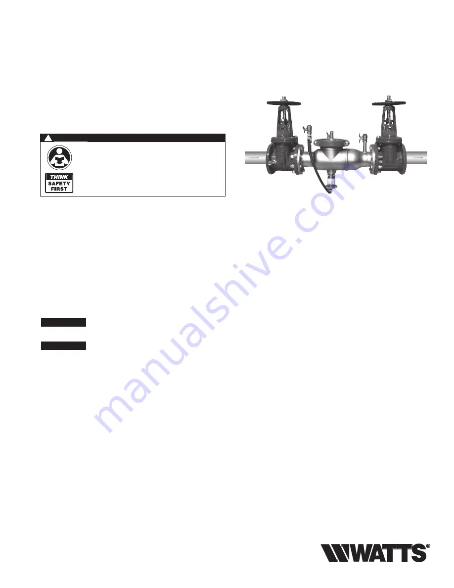
RP/IS-994/994RPDA

NOTICE

Inquire with governing authorities for local installation requirements


NOTICE

For Australia and New Zealand: Pipeline strainers should be installed 

between the upstream shutoff valve and the inlet of the backflow 

preventer.

994

Installation, Maintenance, & Repair 

Series 994/994RPDA

Reduced Pressure Zone Assemblies 

Reduced Pressure Detector Assemblies

Sizes: 2

1

2

" – 10" (65 – 250mm)

Local building or plumbing codes may require modifications to the 

information provided.  You are required to consult the local building and 

plumbing codes prior to installation.  If this information is not consistent 

with local building or plumbing codes, the local codes should be fol-

lowed.

Need for Periodic Inspection/Maintenance:

  This product must be 

tested periodically in compliance with local codes, but at least once per 

year or more as service conditions warrant.  Corrosive water conditions, 

and/or unauthorized adjustments or repair could render the product 

ineffective for the service intended.  Regular checking and cleaning of the 

product’s internal components helps assure maximum life and proper 

product function. 

WARNING

!

Read this Manual BEFORE using this equipment.
Failure to read and follow all safety and use information 

can result in death, serious personal injury, property 

damage, or damage to the equipment.
Keep this Manual for future reference.

Testing

For field testing procedure, refer to Watts installation sheets  

IS-TK-DP/DL, IS-TK-9A, IS-TK-99E and IS-TK-99D found on 

www.watts.com.

For troubleshooting guide, refer to literature S-TSG.
For other repair kits and service parts, refer to our Backflow Preven-

tion Products Repair Kits & Service Parts price list PL-RP-BPD 

found on 

www.watts.com.

For technical assistance, contact your local Watts representative.

Summary of Contents for 994 Series

Page 1: ... with local codes but at least once per year or more as service conditions warrant Corrosive water conditions and or unauthorized adjustments or repair could render the product ineffective for the service intended Regular checking and cleaning of the product s internal components helps assure maximum life and proper product function WARNING Read this Manual BEFORE using this equipment Failure to r...

Page 2: ...may occur due to wa ter supply pressure fluc tu a tion during static no flow con di tions A check valve may be re quired ahead of the backflow preventer 7 ASSEMBLY If the backflow preventer is disassembled dur ing in stal la tion it MUST be reassembled in its proper order The gate valve with the test cock is to mounted on the inlet side of the back flow pre ven ter The test cock must be on the inl...

Page 3: ...from un nec es sary foul ing CAUTION Do not install a strainer ahead of the backflow pre ven ter on seldom used emergency water lines i e fire sprinkler lines The strainer mesh could potentially become clogged with debris pres ent in the water and cause water blockage during an emer gen cy Start Up E The downstream shutoff should be closed Open up stream slow ly fill the valve and bleed the air th...

Page 4: ...osen 2 Check Fin ish un screw ing by hand 3 To clean 1 Check 6 150mm only locate the Check Arm opening stud on the outlet flange of the valve assembly Slide the Check Arm over the stud with the check threads facing down ward figure 5A Tighten 1 4 8mm nut on stud to secure cam bar Slowly pull the assembly outward to open check allowing ex posure of the seat clapper area for clean ing To clean 2 Che...

Page 5: ... certain shutoff valves are closed 1 After removing the first check from the backflow valve body place on a flat surface with the coil spring facing up 2 In order to gain access to the seat and clapper rubber ring you must compress the spring 3 that surrounds the clapper shaft 1 To do so you must place the 3 8 threaded rod through two holes of the spring retaining plate 2 3 After placing the 3 8 a...

Page 6: ...emove the body install a new relief valve assembly 3 Position the diaphragm on the piston assembly so that it is fac ing up as shown in Figure 8 4 Now fold the top ribbed edge of the diaphragm inward grasp the sleeve with the ribbed edge up and slide the sleeve down over the piston assembly as shown in Figure 8 5 While still holding the sleeve slide it up over the diaphragm and using your thumb in...

Page 7: ...art Test 7 Open VA then slowly open VB no more than 1 4 turn When relief valve drips push the hold button for 2 seconds Record reading must be 2 PSID or more Push Stop Test 8 Close VA and VB Test No 2 Test No 2 Check Valve 9 Install bypass hose between VA and TC 4 Open VA then bleed air by loosening hose connection at TC 4 Tighten hose connection Close VA Push Start Test 10 Open VB to reestablish ...

Page 8: ...hin the warranty period the Company will at its option replace or recondition the product without charge THE WARRANTY SET FORTH HEREIN IS GIVEN EXPRESSLY AND IS THE ONLY WARRANTY GIVEN BY THE COMPANY WITH RESPECT TO THE PRODUCT THE COMPANY MAKES NO OTHER WARRANTIES EXPRESS OR IMPLIED THE COMPANY HEREBY SPECIFICALLY DISCLAIMS ALL OTHER WARRANTIES EXPRESS OR IMPLIED INCLUDING BUT NOT LIMITED TO THE ...

Reviews: