background image

19

Pump Tubing Replacement

The black pump tubes may need replacement more often due to the 

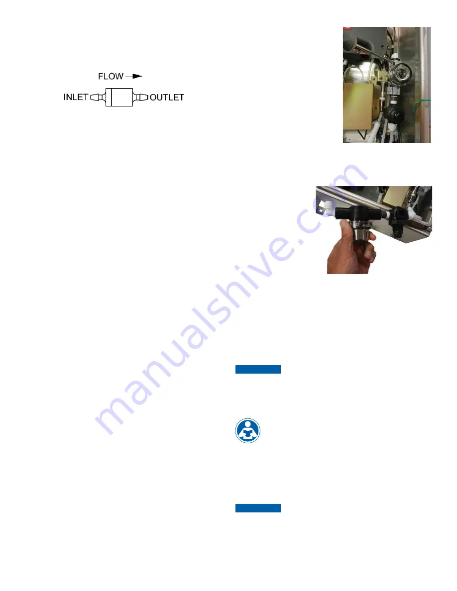
fact that they are subject to wear. The inline check valves should not 

need to be replaced and should be saved. Please note that the check 

valves are directional as shown below.

Figure 5: Inline check valve

Steps:
1.  Flush the system as described above to reduce personal contact 

with the reagents.

2.  Press SERVICE to stop the flow of sample water and drain the 

cuvette.

3.  Remove and retain the thumb screw on top of the pump; pull the 

pump hammer and spring up and out of the way. There is no need 

to completely remove the hammer and spring.

4.  Working on one reagent side at a time. Replace the black tubing 

between optics inlet and the check valve OUTLET. Discard the old tubing.

5.  Ensure the check valve is placed into its seat.
6.  Repeat steps 4 and 5 for the other reagent.
7.  Replace the hammer and spring back into place and secure with the 

thumb screw.

8.  Check the drawing on the following page to ensure correct installation.
9.  Return to operation as described.

Cap Assembly Replacement

When the Cap Assemblies needs to be changed follow the procedure 

shown below. It is recommended that both assemblies are changed at 

the same time.
Steps:
1.  Flush the system as described above to reduce personal contact 

with the reagents.

2.  Press SERVICE to stop the flow of sample water and drain the 

cuvette.

3.  Replace the buffer cap (blue or black cap) assembly.
4.  Repeat step 3 above, for the indicator side (white cap).
5.  Replace reagents, prime and return to service.

Cuvette Replacement

Check the condition of cuvette and change if it appears badly soiled or 

discolored. Follow the steps below.
Steps:
1.  Replace the two Cap Assemblies.
2.  Turn the knurled top on the optics system counterclockwise (as 

viewed for the top) until the cuvette just “pops” out, but do not 

remove the top.

3.  When the cuvette “pops” out, move the retaining O-ring and remove 

the cuvette. You may need a stiff wire such as a bent paper clip 

to grasp the cuvette. Retain this cuvette for future use if it can be 

cleaned.

4.  Install the new cuvette by pushing it firmly in place and turning the 

knurled top clockwise until the cuvette is held securely.

5.  Check the drawing on the following page to ensure correct installation.
6.  Return to operation as described.

T-Strainer Cleaning

The T-strainer is integral to the 

instrument and must be checked 

occasionally. When necessary it 

must be removed and cleaned. 

The strainer screen may require 

replacement after a period of time.
Steps:
1.  Press SERVICE to stop the flow 

of sample water and drain the 

cuvette.

2.  Ensure the source water is 

turned off.

3.  The T-strainer is clamped to the 

intake regulator. The removal 

requires the use of a flat blade screwdriver as shown in the photo. 

Once the two clamps are opened the T-strainer can be removed.

4.  Disconnect the top of the T-strainer and regulator from the tubing 

and clear of the enclosure.

5.  Remove and clean 

the screen and then 

reassemble.

6.  Be sure to tighten the 

bowl of the strainer.

7.  Be certain the clamps 

are tightened fully and 

the tubing connections 

are complete. You may 

require pliers to close 

the clamps.

8.  Turn source water back on.
9.  Return to normal operation.
10. Check for any leaks.

Return to Normal Operation

Press the SERVICE button to return sample flow to the system. 

Check for leaks. If a leak occurs press SERVICE again, repair leak and 

try again. Once the system is operating correctly, return or replace 

reagents and press PRIME and then 

  one time to restart reagent flow. 

The system will automatically return to normal operation.

NOTICE

Tubes may darken due to contact with the reagent. This condition 

does not affect the performance of these parts.

11.2 Replacing or Installing the Reagents

Reagent kits are available from HF scientific for Total 

Chlorine Refer to section 12.0 

Replacement Parts and 

Accessories

 for the appropriate Catalog number. There are 

two reagents required, for the instrument to operate; the 

buffer and the indicator.

The reagents are provided “wet” and the buffer is ready to use and will 

last up to one year.
The smaller indicator reagent does require the addition of the DPD 

power to activate it. Once activated it starts to oxidize. This process is 

slowed by keeping it in the cooling chamber.

NOTICE

When commissioning the CLX-Ex2 it is recommended to follow 

the procedure in section 11.4. This procedure only needs to be 

done once when the instrument first commissioned.

Summary of Contents for 28034

Page 1: ...nded Reagent Life Model CLX Ex2 28034 IOM HF CLX Ex2 28920 WARNING Read this Manual BEFORE using this equipment Failure to read and follow all safety and use information can result in death serious personal injury property damage or damage to the equipment Keep this Manual for future reference IOM HF CLX Ex2 28920 Rev 4 ...

Page 2: ... 7 1 Slope gain Calibration Procedure 12 7 2 Zero offset Calibration Procedure 12 7 3 Restore Factory Settings 12 8 0 Instrument Configuration CONFIG mode 13 8 1 Setting the 4 20 mA 13 8 2 Configuring the Error Level 13 8 3 Configuring the RS 485 Port 13 8 4 Configuring the Alarm 14 8 4 1 Alarm1 14 8 5 Enabling the Security Access 14 8 6 Extended Settings 14 8 7 Units of Measurement 14 8 8 Averagi...

Page 3: ...nstances icons or symbols have been added to give further clarification to the instructions Refer to the Table of Contents to easily find specific topics and to learn about unfamiliar terms This manual is intended to be used in conjunction with No 28749 for more information on the connection and operation of the Air Sentinel 1 1 Symbols Used in This Manual WARNING CAUTION NOTICE 1 2 Use in Explosi...

Page 4: ...ted Communications Port Bi directional RS 485 with Modbus Water Pressure Integral pressure regulator 0 34 bar 5 0 PSI to 10 3 bar 150 PSI Flow Rate to Waste 200 400 ml min Operating Temperature 0 C 55 C 32 F 131 F Wetted Materials PVC Borosilicate Glass Reslyn FFKM Viton FKM Polypropylene 316 Stainless Steel Acetal Noryl Silicone Sample Temperature Range 0 C 55 C 32 F 131 F Power Supply 100 to 240...

Page 5: ...enters the option or mode that is highlighted or chosen The and buttons are used to change settings The PRIME and SERVICE buttons are dedicated controls The PRIME will start 75 reagent pump pulses to prime the tubing after a change or addition of reagent bottles The SERVICE button will drain the instrument and hold all operations until either the SERVICE button is pushed again or the power is rese...

Page 6: ...CLX Ex2 should be removed If the CLX Ex2 is to be turned off it is recommended that the instrument be placed in SERVICE mode before removing power This ensures that the cuvette is emptied and the flow is off 3 2 The Air Sentinel Controller The Air Sentinel controller governs the power to the instrument For normal instrument operation air needs to passes through fitting on the base of the main encl...

Page 7: ... more information on this feature refer to sections 4 4 4 Remote Standby Connections and 6 2 Routine Measurement with Remote Standby 3 5 The Reagent Cooler A reagent cooler is provided for the 125 ml indicator reagent For proper operation power must be applied by the Air Sentinel controller to the cooling chamber temperature controller Clean dry compressed air must also be provided at pressures be...

Page 8: ...ll terminals are designed to accept wires in the range of 14 28 AWG All wires should be stripped to a length of 6 mm For line power connections refer to the companion manual Catalog No 28749 4 4 1 RS 485 The RS 485 half duplex 2 wire digital interface operates with differential levels that are not susceptible to electrical interferences This is why cable lengths up to 3000 ft can be implemented Th...

Page 9: ...ion of the main enclosure with clean dry air Should this air supply pressure fail the PRESSURE lamp on the Air Sentinel unit will turn RED and power to the rest of the instrument is disconnected 5 1 Start Up When power is applied to the CLX Ex2 for the first time ensure that the air supply is connected as stated in section 4 3 and the cabinet is closed and locked Once power is applied the Air Sent...

Page 10: ... chlorine of process water on line The chlorine value of the process water is usually reported in milligrams per Liter mg L these units are equivalent to Parts Per Million PPM The CLX Ex2 has two available measurement ranges 0 00 10 00 or 0 00 15 00 mg L PPM Although the unit will display above the range these readings will not be within the stated accuracy As the reagents degrade due to aging rea...

Page 11: ...s is the number to be changed Use the or arrows to select the first of the three numbers in the code and then press the button to accept the first number of the code Now enter the second number in the code Proceed as with the first number followed by Then repeat the process for the third number in the access code and finish with the button If the valid access code has been selected the instrument ...

Page 12: ...e size of the change that can be made to a current reading The upper limit is the current reading times 1 5 The lower limit is the current reading divided by 1 5 Ensure a reading is posted to the display before calibrating to avoid a nOnE error 7 2 Zero offset Calibration Procedure Generally this calibration is only required if readings are expected to be below 1 mg L or if it is required by a reg...

Page 13: ...evel ERLV The first prompt will be the chlorine limit assigned to the 4 mA output level Select the chlorine level to assign to the 4MA using the and buttons Once the desired level has been set press the button to accept it NOTICE To exit the CONFIG mode press the MODE EXIT button any changes that were made will be saved NOTICE The 4MA can be set higher than 20MA level to invert the output current ...

Page 14: ...the desired UNIT using the and buttons and press the button to accept it 8 8 Averaging and Filtering The CLX Ex2 can display and output averaged readings to help smooth out the response and eliminate large reading variation in rapidly changing processes There are 5 settings for the averaging feature 1 No averaging each reading is in real time 2 The current reading and previous reading are averaged...

Page 15: ... generally not used in ballast water applications and should be set to OFF The instrument requires 110 seconds to complete its normal operations when the WCON is turned On at the factory cycle time the instrument sits idle for about 40 seconds This results in about a 25 water savings The actual amount of water conservation is dependent on the incoming water pressure and the cycle time setting The ...

Page 16: ...0 Additional Features and Options 9 1 RS 485 Outputs The CLX Ex2 has the capability to operate in two different RS 485 modes Included are a simple communication mode and Modbus communications Both modes will automatically configure and do not require any changes or selections 9 1 1 Simple Communication The CLX Ex2 can provide basic communications over simple programs such as the Hilgraeve HyperTer...

Page 17: ...ator can correct and the unit must be returned to the factory for service see section 10 6 These failures consist of failures in the CPU A D EEPROM or other devices internal to the instrument The queued display will show FAIL the upper display will show a four or five digit fault code If this fault occurs it will affect the 4 20mA and any alarm set for fault detection Error The instrument will not...

Page 18: ...Spare Buffer Cap Assembly 1 Spare Indicator Cap Assembly 8 Pump Tubes 1 Spare Cuvette Two replacement sets of reagent cap tubing assemblies are supplied with the CLX Ex2 one for the buffer and one for the indicator Additional kits can be ordered from your local HF scientific distributor or representative It is recommended to keep one kit on hand at all times Generally both pump tubes should be rep...

Page 19: ...urning the knurled top clockwise until the cuvette is held securely 5 Check the drawing on the following page to ensure correct installation 6 Return to operation as described T Strainer Cleaning The T strainer is integral to the instrument and must be checked occasionally When necessary it must be removed and cleaned The strainer screen may require replacement after a period of time Steps 1 Press...

Page 20: ...ds 11 4 Check Valve Flushing Kit Sometimes upon initial commissioning the check valves stick and require manual priming This should not be needed after commissioning Be careful when using this kit to use only chlorine free water Complete instructions are included in the kit Figure 6 Check Valve Flushing 11 5 Instrument Storage If the CLX Ex2 is relocated or will be inactive for long periods of tim...

Page 21: ...d replacement parts Accessory Catalog Number Photo Reagent Kit Total Chlorine 12 month supply 09991 Air Sentinel Purge Control Operating Manual 28749 N A Operating Manual CLX Ex2 28920 N A Tubing Cuvette Kit 09950EX Replacement Cuvette 25018S Check Valve Kit 25017S Ferrite for 4 20mA or RS 485 24560 ...

Page 22: ...ies and replacement parts To order any accessory or replacement part please contact the HF scientific Customer Service Department If for any reason technical assistance is needed regarding this instrument please do not hesitate to contact the HF scientific Technical Services Department HF scientific 16260 Airport Park Drive Suite 140 Fort Myers FL 33913 Phone 239 337 2116 Toll Free 888 203 7248 Fa...

Page 23: ..._ _ _ _ _ _ _ _ _ _ _ _ _ _ _ _ _ _ _ _ _ _ _ _ _ _ _ _ _ _ _ _ _ _ _ _ _ _ _ _ _ _ _ _ _ _ _ _ _ _ _ _ _ _ _ _ _ _ _ _ _ _ _ _ _ _ _ _ _ _ _ _ _ _ _ _ _ _ _ _ _ _ _ _ _ _ _ _ _ _ _ _ _ _ _ _ _ _ _ _ _ _ _ _ _ _ _ _ _ _ _ _ _ _ _ _ _ _ _ _ _ _ _ _ _ _ _ _ _ _ _ _ _ _ _ _ _ _ _ _ _ _ _ _ _ _ _ _ _ _ _ _ _ _ _ _ _ _ _ _ _ _ _ _ _ _ _ _ _ _ _ _ _ _ _ _ _ _ _ _ _ _ _ _ _ _ _ _ _ _ _ _ _ _ _ _ _ _ _ _ ...

Page 24: ...edy for breach of warranty and the Company shall not be responsible for any incidental special or consequential damages including without limitation lost profits or the cost of repairing or replacing other property which is damaged if this product does not work properly other costs resulting from labor charges delays vandalism negligence fouling caused by foreign material damage from adverse water...

Reviews: