ISOMIX HC-IM-DE-W-DE-10-2018-Rev1_enUS | Art. No. 10070436
9
EN
ENGLISH
6.2 Initial commissioning
All screw fittings must be checked and tightened if
necessary prior to installation and commissioning!
Torque:
• ¾” screw fittings 35 Nm
• 1” screw fittings 55 Nm
• 1
1/2
” screw fittings 130 Nm
1. Connect the control station to the pipe network.
2. Shut off the ball valves (using ball valves (15) supplied
with the heating circuit manifold or shut-off device fitted
by the customer).
3. Switch off the pump and close all of the heating circuits
on the distributor.
It is sufficient to close the valves in the return
collector of the heating circuit manifold with the
protection caps.
4. Fill the manifold and control station with hot water (in
accordance with VDI 2035):
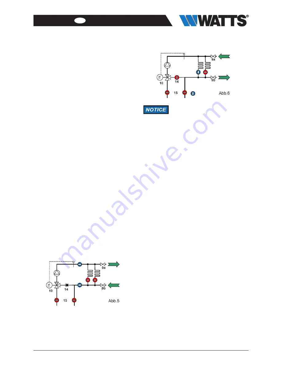
5. connect the filling hose to the fill and drain valve on the
return (5-9b) and the draining hose to the fill and drain
valve on the supply (5-9a).
Heating circuits are closed.
6. Open both fill and drain valves and fill the manifold and
control station until water comes out of the fill and drain
valve on the supply.
7. Close both fill and drain valves.
8. To fill and flush the heating circuits, connect the filling
hose to the supply fill and drain valve (6-9a) and the
emptying hose to the return fill and drain valve (6-9b).
9. Open the heating circuit to be flushed.
10. Open fill and drain valve and flush out the heating circuit
in the direction of flow until the air and any contamination
has been removed from the circuit completely.
The non-return valve (14) in the mixer bypass prevents
any short circuit when flushing.
11. Repeat the process for all the heating circuits.
Flushing is permitted only in the direction
of flow of the heating circuits, i.e. the
water must enter through the flow
manifold and come out of the return!
The drain must always be open, as
otherwise the high water pressure could
damage the heating system.
The instructions on flushing in the
operating manual for the heating circuit
manifold must also be observed.


