
FILENAME
DATE:
B. CREWS
DESCRIPTION:
PAGE
DRAWN BY:
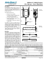
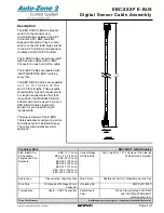
Room Sensor
1
JOB NAME
02/05/03
G-RMSENS1.CDR
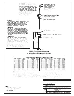
OE210, OE211, OE212, OE213
0.88“
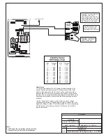
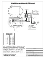
Temperature Sensor Resistance/Voltage Chart
Temp
Resistance* Voltage
F
Ohms
@ Input*
-10.............93333 ........4.620
-5...............80531 ........4.550
0 ...............69822 ........4.474
5 ...............60552 ........4.390
10 ..............52500 ........4.297
15 ..............45902 ........4.200
20 ..............40147 ........4.095
25 ..............35165 ........3.982
30 ..............30805 ........3.862
35 ..............27140 ........3.737
40 ..............23874 ........3.605
°
Temp
Resistance* Voltage
F
Ohms
@ Input*
°
45 ..............21094 ........3.470
50 ..............18655 ........3.330
52 ..............17799 ........3.275
54 ..............16956 ........3.217
56 ..............16164 ........3.160
58 ..............15385 ........3.100
60 ..............14681 ........3.042
62 ..............14014 ........2.985
64 ..............13382 ........2.927
66 ..............12758 ........2.867
68 ..............12191 ........2.810
Temp
Resistance* Voltage
F
Ohms
@ Input*
°
69 ..............11906 ........2.780
70 ..............11652 ........2.752
71 ..............11379 ........2.722
72 ..............11136 ........2.695
73 ..............10878 ........2.665
74 ..............10625 ........2.635
75 ..............10398 ........2.607
76 ..............10158 ........2.570
78 ..............9711 ..........2.520
80 ..............9302 ..........2.465
82 ..............8893 ..........2.407
Temp
Resistance* Voltage
F
Ohms
@ Input*
84 ..............8514 ..........2.352
86 ..............8153 ..........2.297
88 ..............7805 ..........2.242
90 ..............7472 ..........2.187
95 ..............6716 ..........2.055
100 ............6047 ..........1.927
105 ............5453 ..........1.805
110 ............4923 ..........1.687
115 ............4449 ..........1.575
120 ............4030 ..........1.469
°
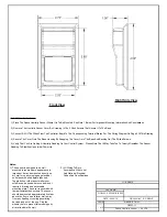
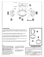
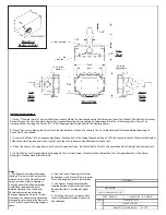
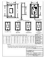
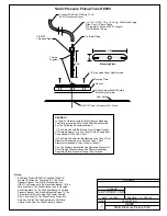
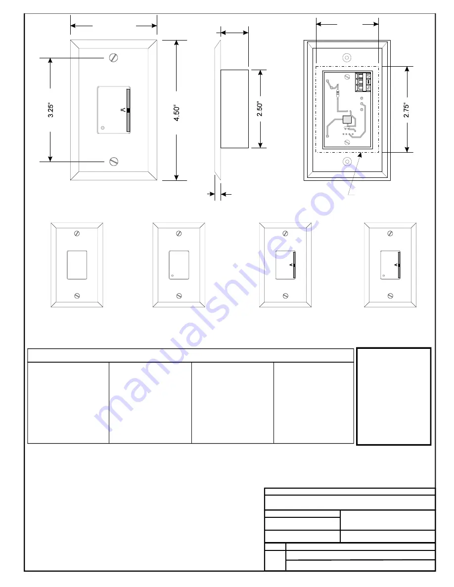
Room Sensor Typical Dimensions
*Chart Notes:
1. Use the resistance column to check the thermistor sensor while disconnected from the controllers (not powered).
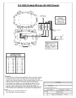
2. Use the voltage column to check sensors while connected to powered controllers. Read voltage with meter set on DC volts. Place the
"-"(minus) lead on GND terminal and the "+"(plus) lead on the sensor input terminal being investigated. If the voltage is above 5.08
VDC, then the sensor or wiring is "open." If the voltage is less than 0.05 VDC, the sensor or wiring is shorted.
O
O
O
A
A
A
O
O
O
R
R
R
L
L
L
M
M
M
E
E
E
E
E
E
C
C
C
W
W
W
R
R
R
R
R
R
OVR
OVR
OVR
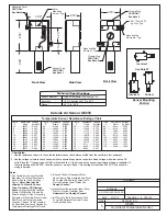
0.25“
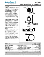
TMP
GND
AUX
OUT
2.00“
Wall Cut-Out Dimensions
When Sensor Is To Be
Mounted Without
Handy Box (By Others)
2.75“
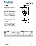
OE210
OE211
OE212
OE213
Room Sensor - Plain
Room Sensor
With Override
Room Sensor
With Setpoint Adjust
Room Sensor
With Setpoint Adjust
& Overide
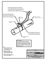
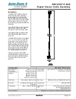
Caution:
The Room Sensor Is
Supplied With A Mylar
Film Coating On The
Sensor Plate That
Protects The Plate From
Marring And Damage
During Shipment And
Installation. After
Installation Of The
Sensor Is Completed,
This Mylar Film Must Be
Removed For Proper
Sensor Operation.


