background image

Watson Industries, Inc. 


ADS-C232-3AD Rev A  10/25/2017 


14 

Appendix A


The following outputs are available via the RS-232 serial link.  Their full-scale ranges are listed for both decimal and 
binary format. 


Inertial Output 

Label 

Full Scale Decimal 

Full Scale Binary 

Time Since Reset 

TM 

65535 

16383 

Bank 

BK 

±179.9º 

±180º 

Elevation 

EL 

±89.9º 

±180º 

X Acceleration 

XA  

±9.99 g 

±10 g 

Y Acceleration 

YA  

±9.99 g 

±10 g 

Z Acceleration 

ZA  

±9.99 g 

±10 g 

X Angular Rate 

XR 

±99.9 º/s 

±200 º/s 

Y Angular Rate 

YR 

±99.9 º/s 

±200 º/s 

Bank Pendulum (simulated) 

XI 

±179.9º 

±180º 

Elevation Pendulum (simulated) 

YI 

±89.9º 

±180º 

Temperature 

TP 

-40º to 88ºC 

-40º to 88ºC (7 bit) 

Flag Bits 

FL 

3 ASCII chars representing Octal 

digits


1 byte 

Status Bits 

ST 

3 ASCII chars representing Octal 

digits


1 byte 

Built In Test (BIT) Status Bits 

BT 

3 ASCII chars representing Octal 

digits


1 byte 

  
The Flag Bits contain the following information: 

Bit 

Description (If Set) 

Bank Error Flag 

Elevation Error Flag 

Unit Temp Out of Range Flag 

BIT Test Flag 

X Rate Out of Range Flag 

Y Rate Out of Range Flag 

Checksum Error Flag 

Unused 


Example: The Flag channel output in ASCII Decimal is “042” 

Octal Digit 

Binary Equivalent 

Flag Bit # 


This translates into the information below: 

Bit 7 

Reset 


Bit 6 

Reset 

No Checksum Error 

Bit 5 

Set 

X Rate Out Range (>140 º/s) 

Bit 4 

Reset 

Y Rate in Range 

Bit 3 

Reset 

No BIT  Error 

Bit 2 

Reset 

Unit Temp in Range (-40º to +85º C) 

Bit 1 

Set 

Elevation Error 

Bit 0 

Reset 

No Bank Error 


Summary of Contents for ADS-C232-3AD

Page 1: ...232 3AD Rev A 10 25 2017 1 Dual Axis Vertical Reference System Owner s Manual PART NUMBER ADS C232 3AD WATSON INDUSTRIES INC 3035 MELBY STREET EAU CLAIRE WI 54703 Phone 715 839 0628 Fax 715 839 8248 Email support watson gyro com ...

Page 2: ...e Main Menu 16 Appendix B 1 Adjust Time Constants 16 Appendix B 2 Set Output Channels 16 Appendix B 3 List Output Channels 17 Appendix B 4 Select Analog Attitude Full Scale Range 17 Appendix B 5 Set Baud Rate 19 Appendix C 20 Watson Industries prides itself on solving customer problems and serving their needs in a timely fashion This manual is intended to facilitate this goal and to provide writte...

Page 3: ...placement for mechanical gyros which are often more expensive and which cannot provide the reliability of a solid state sensor Theory of operation is described with more detail later in this manual The specifications size and pinouts are also described later in this document The Watson Vertical References provide for two types of analog output voltages One is proportional to angular rate and the o...

Page 4: ...induced from other loads on the circuit Theory of Operation In order to obtain an accurate signal in both the short term and in the long term the Vertical Reference relies upon a Watson Industries angular rate sensor ARS combined with solid state accelerometers The position output is generated by integrating the angular rate output This signal is compared with the output from the accelerometer and...

Page 5: ...ation data In most cases these algorithms provide for very stable and accurate output signals however the user should be aware that exceeding the normal ranges of the sensors would affect accuracy For example while custom ADS units may have differing ranges the rate gyros in a typical ADS have a maximum rate of 100 s Care should be taken not to exceed this rate because the closed loop system will ...

Page 6: ...The contents of a typical string are formed as follows See Appendix B for information on how to change the data string 1 A single letter and a space used to indicate the start of the data string The letter I indicates the start of an inertial data string The letter R indicates the start of a Reference data string If the letter is in lower case i or r an error over range condition is indicated see ...

Page 7: ... exists The system will continue to operate in an extended time constant mode with a low level of error accumulation until the condition is cleared Occasional blips of this condition are expected with no detectable affect on the resulting data The other output format available is a binary format The binary format provides generally the same information as the decimal ASCII format but in a compact ...

Page 8: ...t on EEPROM by keying in the quote character Command mode is required for access to this command 9 A command will change the output format to binary This change is made non volatile in the unit on EEPROM by keying in the quote character Command mode is required for access to this command 10 A command will toggle the output to send a frame of data upon receiving any non command character On to Off ...

Page 9: ...ational amplifier Each analog output has a 300 ohm resistor in series to eliminate oscillations from high capacitance loads The output range for all of the analog output channels is 5 Volts with respect to the common signal ground The analog outputs can be found on the 12 pin connector The outputs include Signal Pin Range Output Range 0 VDC Scale Factor Bank X Angle 9 30 5V 0 6 0 V Elevation Y ang...

Page 10: ... Storage 55 C to 85 C Vibration Operating 5g rms 20 Hz to 2 KHz Vibration Survival 10g rms 20 Hz to 2 KHz Shock Survival 500g 1mS sine wave Electrical Frame Rate 250 Hz Maximum Startup Time Data 5 sec Startup Time Fully operational 10 sec Input Power 8 to 45VDC 0 5W Input Current 40mA 12VDC 20mA 24VDC Digital Output RS 232 Analog Output 5VDC Analog Output Impedance 300 Ohm Per line Physical Axis A...

Page 11: ...he signal ground Dimensions X Y X Z Z Y X Y WATSON INDUSTRIES INC www watson gyro com MADE IN U S A P N Rev Pwr S F Figure 2 12 Pin Connector Pin Description 1 RS 232 TXD 2 Y Angular Rate Analog Output 3 Elevation Y Angle Analog Output 4 No Connection 5 Built in Test BIT Output 6 Power Ground 7 RS 232 RXD 8 Signal Ground 9 X Angular Rate Analog Output 10 Bank X Angle Analog Output 11 Factory use D...

Page 12: ... including but not limited to any implied warranty of merchantability or fitness for a particular purpose Excluded from any warranty given by Watson Industries are products that have been subject to abuse misuse damage or accident that have been connected installed or adjusted contrary to the instructions furnished by seller or that have been repaired by persons not authorized by Watson Industries...

Page 13: ... Melby Street Eau Claire WI 54703 ATTN Service Department Telephone 715 839 0628 Fax 715 839 8248 email support watson gyro com Returning the Product Product shall be packaged making sure there is adequate packing around all sides Correspondence shall include Customer s Name and Address Contact Information Equipment Model Number Equipment Serial Number Description of Fault It is the customer s res...

Page 14: ... 3 ASCII chars representing Octal digits 1 byte Status Bits ST 3 ASCII chars representing Octal digits 1 byte Built In Test BIT Status Bits BT 3 ASCII chars representing Octal digits 1 byte The Flag Bits contain the following information Bit Description If Set 0 Bank Error Flag 1 Elevation Error Flag 2 Unit Temp Out of Range Flag 3 BIT Test Flag 4 X Rate Out of Range Flag 5 Y Rate Out of Range Fla...

Page 15: ...de active Bit 2 Bit 1 Bit 0 2 The Current System Time Constant 2 Flag Value 1 2 2 1 2 3 8 seconds The Built In Test BIT Status Bits contain the following information Bit Description 0 If set X Accelerometer Sensor Failure 1 If set Y Accelerometer Sensor Failure 2 If set Z Accelerometer Sensor Failure 3 If set Sensor Temperature out of range 4 If set X Angular Rate Sensor Failure 5 If set X Angular...

Page 16: ...ace bar twice within close succession Note The sensor initialization time begins after the startup message is transmitted Typically this time period lasts 5 seconds but could be as long as 127 seconds depending on your sensor 6 Wait until after initialization is finished At this point command mode will be activated and the unit will accept keyboard commands Note Most Watson sensors have initializa...

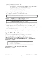
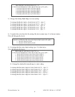
Page 17: ...itting or updating the new channels to restart the data flow Appendix B 3 List Output Channels 1 To list the current output channel selection type 3 at the main menu 2 The sensor will show which channels are currently active Appendix B 4 Select Analog Attitude Full Scale Range 1 To update the scale factor for the analog Bank output type 4 at the main menu This will bring up the menu 2 To change th...

Page 18: ...1 To change the Elevation Angle to Scale Factor 9 0 V type 2 To change the Elevation Angle to Scale Factor 12 V type 3 To change the Elevation Angle to Scale Factor 18 V type 4 To change the Elevation Angle to Scale Factor 36 V type 5 THE CURRENT SETTING IN DEG V IS 6 0 TYPE IN THE NUMBER OF YOUR SELECTION OR Q TO QUIT 1 BANK ANGLE SCALE FACTOR 6 0 DEG V 2 BANK ANGLE SCALE FACTOR 9 0 DEG V 3 BANK ...

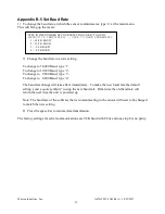
Page 19: ... immediately To make the new baud rate the default setting send a quote symbol using the new baud rate Otherwise the old baud rate will return the next time the unit is powered up Note The baud rate of the software that is communicating to the sensor will need to be changed to match the new setting 8 Press the space bar to resume data transmission The factory settings for serial communications are...

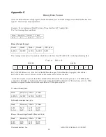
Page 20: ...plus 6 bits of data Bit 7 of the LSB is set to 1 Bits 6 to 0 of the LSB are the lower 7 bits of the data As the data words are received the LSB is shifted left to shift out the 7th bit always set to 1 The MSB is then connected to the LSB as a 16 bit word This word is then shifted left to shift out the 7th bit always set to 1 What remains is a signed fractional word with a resolution of 13 bits plu...

Page 21: ...en subtract 65536 from the data Bank Elevation X Rate Y Rate 2728 912 1668 508 Multiply the data in counts by the scale factor Convert to units counts scale factor For Bank Elevation Scale factor is 180 32768 counts For Angular Rate Scale factor is 200 s 32768 counts Bank Elevation X Rate Y Rate 14 991 5 010 10 181 s 3 100 s The nominal interface settings are 9600 Baud 8 Bit Data 1 Start Bit 1 Sto...

Reviews: