Watson Desking Miro Conference MCVSQR Series Product Installation Download Page 2

48"W & 60"W Conference Tables -

MCVREC48XX, MCVREC60XX,
MCVREPXXXXX

Page 1 of 8

PRODUCT INSTALLATION:

INS31006

MIRO CONFERENCE

WATSON DESKING

800.426.1202

www.watsondesking.com
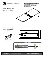
Step 2

Fasten support tube to Viga corner legs
using 1/4-20 x 1/2" low profile head hex drive
bolts (FIG-1).  Bolts require M4 hex bit.
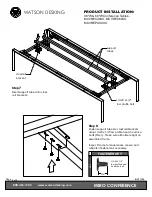
Step 1 - 

For 10' and 12' tables

Assemble 2 Viga legs by sliding triangular Viga spanner
tube and square support tube into Viga corner legs.

support tube

Viga

corner

leg

Viga

spanner

tube

support tube

FASTENER KEY

F

IG

-1

1/4-20 x 1/2"

low profile head
hex drive bolt

1/2"

Viga
spanner
tube

Make sure to assemble Viga legs
on a flat surface and that Viga
spanner tube and Viga corner
leg are snug with no gaps.

Caution:  Take care not to
scratch paint.

1/4-20 x 1/2"

low profile bolt

must be

parallel

Note

Summary of Contents for Miro Conference MCVSQR Series

Page 1: ......

Page 2: ...bit Step 1 For 10 and 12 tables Assemble 2 Viga legs by sliding triangular Viga spanner tube and square support tube into Viga corner legs support tube Viga corner leg Viga spanner tube support tube...

Page 3: ...1 4 20 x 1 2 low profile head hex drive bolts FIG 1 Step 3 for all tables On one Viga leg insert both cross rails into brackets FASTENER KEY FIG 1 1 4 20 x 1 2 low profile head hex drive bolt 1 2 Viga...

Page 4: ...1 2 Step 6 Fasten cross rails on partially assembled frame to Viga leg brackets using 1 4 20 x 1 2 low profile head hex drive bolts FIG 1 Step 5 With a partner flip partially assembled frame over and...

Page 5: ...pport tubes to cross rail brackets using 1 4 20 x 1 2 low profile head hex drive bolts FIG 1 Make sure all bolts are tight on assembled frame Inspect frame for squareness Loosen and retighten fastener...

Page 6: ...table surface FASTENER KEY FIG 2 10 x 3 4 wood screw 3 4 Step 10 Align table top with assembled frame making sure corners of table surface are square with frame Fasten table surface to assembled frame...

Page 7: ...for seamed tables Place other half of table top on to frame and mate to first half FASTENER KEY FIG 3 flip bolt Flip Bolt locations Step 13 for seamed tables Lock table top halves together with flip...

Page 8: ...sure all top to leg relationships are the same FASTENER KEY FIG 2 10 x 3 4 wood screw 3 4 Step 15 Fasten table top to assembled frame using 10 x 3 4 wood screws FIG 2 Tighten screws sequentially from...

Page 9: ...end of table to aid in installation of center leg Align leg with pilot holes in center of table Center leg plate will capture support tubes FASTENER KEY FIG 2 10 x 3 4 wood screw 3 4 Step 17 for 10 an...

Reviews: