

2
RECOMMENDATIONS
1. When possible, install two 45-degree angles to create a right angle rather than one 90-degree angle.
2. Be sure to install the loop (see installation section) a minimum of 12" to 18" above spa level.
3. Use a check valve in every system.
TYPICAL INSTALLATION OF THE BLOWER
By following the installation recommendations listed below you will be assured of optimum performance and a
long lasting installation. Blower model numbers starting at 750 offer the option of side or bottom air discharge.
They are supplied with plug for mounting. An external anti-surge valve (sold separately) can be used to prevent
potential water backflow to the blower.
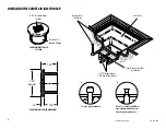
When using the side discharge, screw the plug to a solid base using the (3) screw holes
provided (see Diagram 2). Apply a small amount of silicone to the vertical wall of the plug
and set the blower housing on the plug. If gluing is necessary, spot glue only.
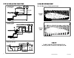
For bottom discharge, the 2" pipe may be used as the blower support. Be sure to keep the
blower 12" to 18" above water level and use the Hartford loop system with a check valve
(see Diagram 1). Again, a bead of silicone around the pipe will hold the unit firmly in place.
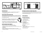
ELECTRICAL HOOKUP (SEE DIAGRAM 3)
1. Check the line voltage to be sure it is correct for the air blower being used.
2. DO NOT connect 220 volt line to 110 volt unit. THIS WILL DESTROY YOUR BLOWER.
3. If switch is used, install as illustrated. If switch is not used, tie one line to one load, tie the other line (or neutral)
to the other load.
4. GROUND ALL UNITS.
5. ADDITIONAL GROUNDING NOTE: Double insulated (plastic) blowers do not need to be bonded.
6. If the supply cord is damaged, it must be replaced by the manufacturer, its service agent or similarly qualified
person in order to avoid a hazard.
AMPERAGE TEST FOR SPOT CHECKING INSTALLATION
To insure a properly installed and sized air blower, complete the following test. Pull the blower off the pipe, start
the unit, and read the amperage. Set blower back on the pipe, start the unit, wait for air channel to clear, and read
amperage again. A properly installed unit will not drop more than .5 amps. If the amperage is not to within the
range, refer to Troubleshooting or Sizing sections.
TROUBLESHOOTING
NO ACTION OR TOTAL MOTOR FAILURE
1. Check motor brushes for excessive wear.
2. Check wiring (i.e. voltage, amperage, etc.)
3. Check for blockage in plumbing.
4. Be sure sizing is correct.
5. Be sure check valve is installed properly.
BLOWER OVERHEATING
1. Check for blockage in plumbing.
2. Be sure sizing is correct.
3. Be sure check valve is installed properly.
WATER DAMAGE
1. Check valve may be failing.
2. Sprinklers close to air blowers causing water entry through air intake.
3. Blower installed below water level.
4. Blower installed upside down.
DIAGRAM 1
DIAGRAM 3
Grade
32"
36"
Check
Valve
Blower
32"
32"
12" - 18"
5 ft. min
25 ft. max
20"
Hartford Loop
Grade Level
30 ft. total Air Line
2" PVC Air Line
DIAGRAM 2
NEUTRAL
LOAD
LINE
NEUTRAL
CHASIS SCREW
GROUND #12AWG
LOAD
LOAD
LINE
LINE
GROUND
CHASIS SCREW
GROUND #12AWG
GROUND
110 VOLT
220 VOLT
810-0037.0618
©2018 Waterway Plastics


