background image

4

INSTALLATION

FILTER MOUNT MUST:


•   Provide weather and freezing protection. 


•   Provide space and lighting for easy access for routine    


 maintenance. 


•   Provide ventilation and drainage for pump. 


•   Be on a reasonably level surface and provide adequate    


 drainage.

PIPING: 

NOTICE:

 Make sure that the filter and all piping can be drained for 

winterizing. See “Winterizing”, page 6.

NOTICE:

 Overtightening can crack filter ports.

Use Teflon tape, Plasto-Joint Stik®

 or Silastic RTV #732® on all threaded 

connections of plastic pipe and fittings.

DO NOT use pipe compounds on filter; it will cause the 

connection to crack. Do not use sealant on unions; assemble 

them dry and hand tight.

Support pipe independently to prevent strains on the filter.
Keep piping tight and free of leaks. Pump section line leaks may cause 
trapped air in filter tank or loss of prime at pump.

† Lake Chemical Co., Chicago, Ill.

ELECTRICAL:

Be sure that pump grounding meets local and National Electrical Code 
Standards. All wiring and grounding of associated equipment must 
meet local and National Code Standards.

INITIAL START-UP

Be sure pump is OFF before starting procedure.

Do not operate filter at more than 50 PSI (345 kPa).

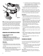
1. Securely lock the Pro-Clean Ring in place by rotating it CLOCKWISE  
  until it “clicks” past the safety latch (see Figure 3). Stop turning as    
  soon as the ring clicks past the latch. The ring may feel slightly  
  loose, but it will tighten up when the pump is on and the filter is    
  under pressure.
2. Install the pressure gauge and the air release valve (see Figure 2) on  
  the tank lid.
3.  Fill the trap on the pump with water.
4. Open the air release valve on top of the filter.

5. Open valves separating the filter from the rest of the system.
6. Start the pump to purge air from the system.
7. When a steady stream of water comes from the air release valve,    
  close the valve.

NOTICE:

 Leaking around the filter ring may indicate that the ring is not 

fully locked. In this case proceed as follows:
    A. Stop the pump and open the air release valve then release    
      any pressure within the filter.
    B. Remove the drain plug and drain all water from the filter.
    C. Rotate the filter ring clockwise until it locks behind the  


      safety latch (see Figure 3).
    D. If the ring was already locked, remove it and the filter lid    
      assembly. Inspect and clean the O-ring and all sealing surfaces.  
      Re-lubricate the O-ring, if necessary.

NOTICE:

 Lubricate the O-ring sealing area inside the upper tank lip 

with silicone grease, as other lubricants may cause the ring to swell. DO 
NOT lubricate the filter ring or the threads on the tank shell as this may 
collect grit and make removal difficult.

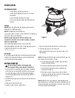
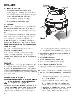
Air Relief 

Valve

Pressure

Gauge

Filter Ring

Latch

Figure 2

Summary of Contents for proclean plus PCCF-075

Page 1: ...PCCF 075 PCCF 100 PCCF 125 PCCF 150 PCCF 175 PCCF 200 2200 East Sturgis Road Oxnard CA 93030 Phone 805 981 0262 Fax 805 981 9403 www waterwayplastics com waterway waterwayplastics com Designed Enginee...

Page 2: ...75 6 96 100 9 2 125 11 6 150 13 9 175 16 2 200 18 6 Max Residential Flow Rate GPM LPM 75 284 100 379 125 473 150 568 150 568 150 568 Max Public Pool Flow Rate GPM LPM 28 106 37 148 47 177 56 212 65 24...

Page 3: ...normally be cleaned when the pressure gauge reading increases 10 PSI over the start up pressure In some pools accessories such as fountains or pool cleaners may be noticeably affected by the normal de...

Page 4: ...KWISE until it clicks past the safety latch see Figure 3 Stop turning as soon as the ring clicks past the latch The ring may feel slightly loose but it will tighten up when the pump is on and the filt...

Page 5: ...SEMBLY 1 Inspect and clean the tank ring threads and O ring groove Replace damaged parts as necessary 2 Install the filter cartridge in the tank Push down firmly to seal it NOTICE Lubricate the O ring...

Page 6: ...er Solvents may damage plastic components in the system NOTICE Open the air release valve and bleed all air from the filter each time the filter is drained or disassembled WEEKLY INSPECTION 1 Remove d...

Page 7: ...nal C Excessive air in filter vent air from tank and check for pump suction pipe leaks Clean air bleed tube in cartridge assembly D Pool water contains iron consult your pool professional E Heavy or i...

Page 8: ...0701 Lock Ring Assembly 4 500 7310 Screen Sock w Clamp Assy 5 872 4000E Air BleedTube 75 100 sq ft 872 4000L Air BleedTube 125 150 sq ft 872 4000F Air BleedTube 175 200 sq ft 6 817 0075P Filter Cartr...

Page 9: ...OD LES PCCF 075 PCCF 100 PCCF 125 PCCF 150 PCCF 175 PCCF 200 2200 East Sturgis Road Oxnard CA 93030 Phone 805 981 0262 Fax 805 981 9403 www waterwayplastics com waterway waterwayplastics com Designed...

Page 10: ...lb po2 kPa COURBE DES CHUTES DE PRESSION DETOUS LES MOD LES PCCF PCCF 075 D bit max PCCF 100 D bit max PCCF 125 D bit max PCCF 150 D bit max PCCF 175 D bit max PCCF 200 D bit max Table 1 Sp cification...

Page 11: ...0 lb po par rapport la pression de mise en service Dans certaines piscines des accessoires comme des fontaines ou des nettoyeurs automatiques de piscine peuvent tre consid rablement affect s par une d...

Page 12: ...aisons m talliques de l quipement connexe doivent tre conformes aux normes du National Electrical Code du code Canadien de l lectricit et ou de la municpalit MISE EN SERVICE INITIALE S assurer que la...

Page 13: ...pr t le remplacer Pour le d poser le sortir de sa goge avec un fil de fer rigide courb son extr mite que l on introduira dans la petite fente d acc s qui se trouve la partie inf rieure du couvercle d...

Page 14: ...produits risquent d endommager les composants en plastique du syst me NOTE Ouvrir le purgeur d air et chasser tout l air du filtre chaque fois que l on arr te la pompe puis qu on la remet en marche I...

Page 15: ...ulter un professionnel en piscines C Quantit d air excessive dans le filtre Nettoyer le tube de purge d air de la cartouche filtrante D L eau de la piscines contient du fer Consulter un professionnel...

Page 16: ...3 550 0701 La Bague deVerrouillage Assemblage 4 500 7310 cran Chaussette avec Pince Assemblage 5 872 4000E Tube de Purge d air 75 100 pi ca 872 4000L Tube de Purge d air 125 150 pi ca 872 4000F Tube...

Page 17: ...LOS PCCF 075 PCCF 100 PCCF 125 PCCF 150 PCCF 175 PCCF 200 810 0161 EFS 0320 2020 Waterway Plastics 2200 East Sturgis Road Oxnard CA 93030 Phone 805 981 0262 Fax 805 981 9403 www waterwayplastics com w...

Page 18: ...i n en lb pulg cuadrada psi kPa CURVA DE CA DA DE PRESI N PCCF 075 caudal m x PCCF 100 caudal m x PCCF 125 caudal m x PCCF 150 caudal m x PCCF 175 caudal m x PCCF 200 caudal m x Table 1 Especificacion...

Page 19: ...ro se debe limpiar generalmente cuando la lectura del man metro aumenta 10 lb pulg duadrado psi por encima de presi n de inicio En ciertas piscinas es posible que a medida que el filtro se ensucia el...

Page 20: ...e las m quinas deber n cumplir con las normas locals y las del National Electrical Code ARRANQUE INICIAL Antes de comenzar el procedimiento de aranque verifique que la bomba est apagada Nunca opere el...

Page 21: ...ea necesario reemplazarlo Para sacarlo eng nchelo y s quelo de su canaleta con un trozo curvo y r gido de alambre introducido en la ranura de acceso peque a que se encuentra en la parte inferior de la...

Page 22: ...a y vuelva a encender la bomba abra la v lvula de descarga de aire y purgue todo el aire del filtro INSPECCI N SEMANAL 1 Elimine la suciedad de la cesta de la espumadera de la piscina 2 Pare la bomba...

Page 23: ...Ventile el aire del tanque y verifique que el tuber a de aspiraci n de la bomba no tenga fugas Limpie el tubo de purga de aire en la unidad del cartucho D El agua de la piscina contiene hierro consul...

Page 24: ...blea de la Anilla de Cierre 125 150 p c incluye 1A 1E 550 0631 Tapa del Filtro y Asamblea de la Anilla de Cierre 125 200 p c incluye 1A 1E 1A 600 0220 V lvula del Lanzamiento del Aire con el Anillo O...

Reviews: