background image

Fluid-Handling Components

28

1

Drip tray

Catches fluid leaks.

Drip tray waste exit

Drains accumulated fluids to the waste container.

Gradient mixer

Increases homogeneity. Also adds volume to the system.

Inlet and outlet check 
valve assemblies

Maintain flow direction and pressure by opening in one 
direction only.

Inlet manifold

Provides the connection for eluent inlet tubing and routes 
eluent to the inlet check valve on each pump head.

Manual injector

Enables a manual sample injection. Generates an inject 
start signal to the detector.

Manual injector waste line 
(1525EF Pump)

Routes flow from the manual injector to the waste container.

Plunger indicator rods

Show the position of each pump head plunger.

Pressure transducer

Senses operating pressure and converts values to elec-
tronic signals for monitoring.

Pulse dampeners

Dampen operating pressure fluctuations. Located on the 
left side of the unit under the mixer and behind the shroud.

Pump head assembly

Draws in and delivers eluent. Defines pump capacity.

Pump outlet

Routes eluent to the injector, column, and detector.

Reference (or vent) valve

Directs flow from the pump to waste for purging, or through 
the injector, the column, and the rest of the system.

Reference (or vent) valve 
waste line

Routes flow from the reference (or vent) valve to the waste 
container.

Restrictor tee 
(1525µ Pump)

Blends two solvents together (with backflow prevention).

Seal wash holes
(not visible in 

Figure 1-3

 or 

Figure 1-4

)

Allow manual flushing of plunger seals.

Tee (1525EF Pump)

Blends two solvents together.

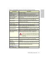
Table 1-1  Fluid-Handling Components in the Waters 1525 Pump (Continued)

Component

Description

Caution: 

To prevent eluent from leaking out of the 

pump outlet, position the eluent reservoir below the 
pump inlet manifold before disconnecting the pump 
outlet fitting.

Summary of Contents for 1525M

Page 1: ...Waters 1525 and 1525EF HPLC Pump Installation and Maintenance Guide 34 Maple Street Milford MA 01757 71500152504 Revision A...

Page 2: ...this document 2003 WATERS CORPORATION PRINTED IN THE UNITED STATES OF AMERICA ALL RIGHTS RESERVED THIS DOCUMENT OR PARTS THEREOF MAY NOT BE REPRODUCED IN ANY FORM WITHOUT THE WRITTEN PERMISSION OF THE...

Page 3: ...ould void the user s authority to operate the equipment Important Toute modification sur cette unit n ayant pas t express ment approuv e par l autorit responsable de la conformit la r glementation peu...

Page 4: ...trouvant proximit N utilisez pas de tuyau de Tefzel fortement ab m ou d form N utilisez pas de tuyau de Tefzel avec de l acide sulfurique ou nitrique ou du t trahydrofurane THF Sachez que le chlorure...

Page 5: ...lsolfossido provocano rigonfiamento nei tubi Tefzel che riducono notevolmente il limite di pressione di rottura dei tubi stessi Advertencia manipular con precauci n los tubos de pol mero bajo presi n...

Page 6: ......

Page 7: ...d fectueuses Vorsicht Der Benutzer wird darauf aufmerksam gemacht dass bei unsachgem er Verwenddung des Ger tes unter Umst nden nicht ordnungsgem funktionieren Precauzione l utente deve essere al corr...

Page 8: ...d viter tout risque d incendie Vorsicht Zum Schutz gegen Feuergefahr die Sicherungen nur mit Sicherungen des gleichen Typs und Nennwertes ersetzen Precauzione per una buona protezione contro i rischi...

Page 9: ...d effectuer la maintenance de l instrument Vorsicht Zur Vermeidung von Stromschl gen sollte das Ger t vor der Wartung vom Netz getrennt werden Precauzione per evitare il rischio di scossa elettrica sc...

Page 10: ...continua Corriente continua Alternating current Courant alternatif Wechselstrom Corrente alternata Corriente alterna Protective conductor terminal Borne du conducteur de protection Schutzleiteranschl...

Page 11: ...au guide Vorsicht oder lesen Sie das Handbuch Prestare attenzione o fare riferimento alla guida Act e con precauci n o consulte la gu a Caution hot surface or high temperature Attention surface chaud...

Page 12: ...ica alta tensi n Caution risk of needle stick puncture Attention risques de perforation de la taille d une aiguille Vorsicht Gefahr einer Spritzenpunktierung Precauzione rischio di puntura con ago Pre...

Page 13: ...on Sous tension Netzschalter ein Alimentazione elettrica attivata Alimentaci n el ctrica conectada Electrical power off Hors tension Netzschalter aus Alimentazione elettrica disattivata Alimentaci n e...

Page 14: ...potentially infectious Precautions are outlined in CDC Guidelines on Specimen Handling CDC NIH Manual 1984 Calibration Follow acceptable methods of calibration with pure standards to calibrate methods...

Page 15: ...Connections 34 2 3 1 Connecting the Power Supply 34 2 3 2 Setting the IEEE 488 Address 34 2 3 3 Making IEEE 488 Connections 36 2 4 Making Fluidic Connections 37 2 4 1 Making Eluent Supply Connections...

Page 16: ...2 Ramp and Decay Test 53 4 3 Replacing 1525 Plunger Seals and Plungers 55 4 3 1 Preparing for Plunger Seal Replacement 55 4 3 2 Removing and Replacing the 1525 Plunger Seal 57 4 3 3 Cleaning and Repla...

Page 17: ...cifications 88 Appendix B Spare Parts and Accessories 92 Appendix C Solvent Considerations 96 C 1 Introduction 96 C 2 Solvent Compatibility 97 C 3 Solvent Miscibility 99 C 4 Buffered Solvents 102 C 5...

Page 18: ...igurations 41 2 5 Standard Ferrule and Compression Screw Assembly 44 3 1 Priming the Pump 49 4 1 Unscrewing Pump Head Mounting Screws 1525 Pump 57 4 2 Exposed Head Support Assembly 1525 Pump 59 4 3 Di...

Page 19: ...Heater 88 A 3 Environmental Specifications 89 A 4 Electrical Specifications 89 A 5 Performance Specifications for the 1525 Pump 90 A 6 Performance Specifications for the 1525EF Pump 90 B 1 Spare Part...

Page 20: ...ist of Tables 20 C 6 UV Cutoff Wavelengths for Common Chromatographic Solvents 105 C 7 Wavelength Cutoffs for Different Mobile Phases 106 C 8 Refractive Indices for Common Chromatographic Solvents 107...

Page 21: ...nd options Chapter 2 explains how to unpack and install Waters 1525 HPLC Pumps Chapter 3 describes how to power on the pump purge the pump and power off the pump Chapter 4 covers routine maintenance d...

Page 22: ...ent titles For example Replace file_name with the actual name of your file Courier Courier indicates examples of source code and system output For example The SVRMGR prompt appears Courier Bold Courie...

Page 23: ...should choose each option in sequence For example Select File Exit means you should select File from the menu bar then select Exit from the File menu STOP Attention To avoid damaging the detector flo...

Page 24: ...d functions equally well The 1525 Binary HPLC Pump is designed for precise reproducible gradient delivery at low flow rates up to 5 mL minute Figure 1 1 The 1525EF Binary HPLC Pump is designed for inc...

Page 25: ...Overview 25 1 Figure 1 2 Waters 1525EF Pump with an Optional Column Heater TP01722 Bottle Holder Column Heater...

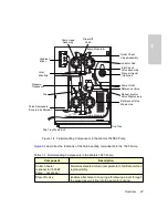
Page 26: ...1 3 and Figure 1 4 Figure 1 3 Fluid Handling Components in the Waters 1525 Pump Gradient Mixer Inlet Manifold Restrictor Tee Patent Pending Pressure Transducer Pulse Dampeners Covered by Shroud Pump...

Page 27: ...e to facilitate method reproducibility Draw off valve Enables attachment of a syringe for drawing eluent through the eluent reservoir line into the pump for priming Reference Valve Outlet Check Pump H...

Page 28: ...r monitoring Pulse dampeners Dampen operating pressure fluctuations Located on the left side of the unit under the mixer and behind the shroud Pump head assembly Draws in and delivers eluent Defines p...

Page 29: ...ents as illustrated in Figure 1 5 Figure 1 5 Rear Panel Electronic Components in the Waters 1525 Pump Ethernet Port Power Cord Power Switch Fuse Holder Side of Unit I O Terminal Block IEEE 488 Port IE...

Page 30: ...ection 3 2 1 on page 48 Table 1 2 Electronic Components in the Waters 1525 Pump Component Description Cooling fan vent Exhausts air for cooling internal electronics Ethernet port Provides an Ethernet...

Page 31: ...dity 20 to 80 noncondensing Bench space Width 17 in 43 cm including bottle holder 24 in 61 cm with column heater Depth 24 in 61 cm Height 17 in 43 cm Vibration Negligible Clearance Minimum 6 in 15 cm...

Page 32: ...Installing the 1525 Pump 32 2 Figure 2 1 Pump Dimensions 24 in 12 in 17 in 43 cm 7 in 5 in Clearance for Optional Column Heater Clearance for Bottle Holder 61 cm...

Page 33: ...Check the contents of the Startup Kit against the Startup Kit parts list to confirm that all items are included 6 Verify that the serial number on the inside left frame of the pump matches the serial...

Page 34: ...the Power Supply The 1525 and 1525EF Pumps automatically adjust for AC input voltage To make the power supply connection 1 Insert the 120 V or 240 V power cord into the power cord connection on the r...

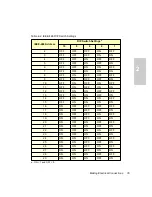
Page 35: ...ON ON ON 8 OFF ON OFF OFF OFF 9 OFF ON OFF OFF ON 10 OFF ON OFF ON OFF 11 OFF ON OFF ON ON 12 OFF ON ON OFF OFF 13 OFF ON ON OFF ON 14 OFF ON ON ON OFF 15 OFF ON ON ON ON 16 ON OFF OFF OFF OFF 17 ON O...

Page 36: ...ble length to connect the devices and the GPIB connector in one interface system is 2 meters 6 5 feet times the number of devices or 20 meters 65 feet whichever is smaller The maximum cable length bet...

Page 37: ...IEEE 488 device 5 Make sure that all IEEE 488 cable connector screws are finger tight 2 4 Making Fluidic Connections This section describes how to make fluidic connections to a Waters 1525 Pump by Mak...

Page 38: ...rews on the pump 2 Holding the rack flush against the surface of the pump finger tighten the captive screw to secure the rack Connecting Eluent Tubing to the Pump Inlet 1 Measure the length of 1 8 inc...

Page 39: ...g on the solvent filter into the open end of this tubing 5 Install the cap onto the eluent reservoir and push the tubing through the cap until the filter reaches the bottom of the reservoir 6 Repeat s...

Page 40: ...assing the Mixer in the 1525 Pump on page 42 Note Removing the mixer will result in an increase of the gradient ripple and baseline noise 1525EF HPLC Pump The 1525EF Pump is shipped with one large vol...

Page 41: ...g holes on the upper left side of the chassis face For the following configurations these hole pairs are numbered from 1 to 4 top to bottom Dual GM150 Gradient Mixers To use this configuration with th...

Page 42: ...xer in the 1525 Pump 1 Disconnect the tubing running from the bottom of the pressure transducer to the gradient mixer 2 Disconnect the tubing running from the mixer to the vent valve 3 Connect the pre...

Page 43: ...part number WAT025604 in Startup Kit 1 16 inch OD stainless steel tubing in Startup Kit Circular tubing cutter part number WAT022384 or knife edge file Needle nose pliers two pairs if cutting tubing w...

Page 44: ...ess steel tubing Making the Connections 1 While pressing one end of the tubing assembly into the pump outlet fitting finger tighten the compression screw then use the 5 16 inch wrench to tighten the s...

Page 45: ...tubing parallel with the drip tray see Figure 1 3 or Figure 1 4 and secure it in the provided spring clips 4 Insert the reference valve waste line and the optional manual injector waste lines together...

Page 46: ...ces before powering on the MassLynx workstation 3 Power on the MassLynx workstation and log on to Windows 4 Select Start Programs MassLynx MassLynx V4 0 The MassLynx Main window appears 5 Click the In...

Page 47: ...ents for example cyclohexane solidifies at 3 5 K psi Consider column chemistry If the column can be damaged by an intermediate or new eluent remove the column from the system and substitute a union Re...

Page 48: ...ars 4 Click Status to get the LC status 5 Click the Inlet Method button left side of the window to open the Inlet Editor window 6 Click the Inlet icon to go to the pump method 7 Set the flow rate For...

Page 49: ...ssure for the selected eluent and flow rate If the pump pressure is not correct repeat steps 2 through 6 to reset the flow rate as necessary 14 Click the Start Stop Pumping icon in the Inlet Method wi...

Page 50: ...e rate to 3 0 mL min If the pump is dry start with a lower flow rate Note These flow rates may not be appropriate for all columns 8 Click Save in the Inlet Method window to save the method 9 Click Loa...

Page 51: ...ing powering off the pump will stop flow immediately 3 Set the power switch to the 0 OFF position STOP Attention Since abrupt flow changes can damage columns it is advisable to ramp flow to 0 using an...

Page 52: ...ting procedures and guidelines in Section 3 2 Preparing the Pump Caution To prevent injury always observe good laboratory practices when handling eluents changing tubing or operating the 1525 HPLC Pum...

Page 53: ...me stability test Ramp and decay test 4 2 1 Retention Time Stability Test Observing retention time stability during system performance monitoring tests is useful for determining the performance of you...

Page 54: ...ure limit 1525 Pump 5000 psi 41 370 kPa 401 bar 1525EF Pump 5000 psi 34 475 kPa 334 bar 8 With the 100 methanol reservoir still connected to the pump inlet click Load Method in the Inlet Method window...

Page 55: ...he pulse dampener 15 Repeat steps 3 through 14 on pump B In step 3 disconnect pump A from the tee 16 When finished purge the pump with eluent and close the reference or vent valve 17 Remove the compre...

Page 56: ...to the Inlet Method window Set the Flow parameter to 0 3 mL min click Save then click Load Method to run the pump 6 After the indicator rod fully retracts into the pump head click the Stop Flow butto...

Page 57: ...cing away from the end of the tool you should be able to see the seal spring at the tip of the tool 4 Moisten the seal with methanol 5 Place the small end of the block part of the seal insertion tool...

Page 58: ...d in Section 3 2 1 on page 48 If you notice leaks verify pump head and plunger seal installation If necessary repeat these procedures removing the pump head and replacing plunger seals for the other p...

Page 59: ...he plunger is fully extended click the Stop Flow button to stop the pump 4 Remove the plunger by sliding it out of the back of the support assembly Set the support assembly aside Continue with Cleanin...

Page 60: ...th high pressure grease Make sure the brass seat is located at the bottom of the piston 3 Reinstall the assembled plunger into the support assembly 4 Use the software to navigate to the Inlet Method w...

Page 61: ...10 Use the 1 2 inch adjustable wrench to hold the check valve housings in place Reconnect the inlet and outlet tubing assemblies to the pump head 11 Prime the pump as described in Section 3 2 1 on pag...

Page 62: ...Note To help keep the cartridge seated within the housing moisten it with methanol during installation 5 With the housing held upright to prevent the cartridge from falling out finger tighten the hou...

Page 63: ...ngs 4 Use the 1 2 inch adjustable wrench to loosen the outlet check valve housing 5 While holding the pump head securely against the pump use the 5 32 inch Allen wrench to remove the two pump head ass...

Page 64: ...wrench 14 Prime the pump as described in Section 3 2 1 Check for leaks Replacing the Restrictor Tee Check Valves To replace the restrictor tee check valves follow the procedure in Replacing the Inlet...

Page 65: ...2 turn to open the valve 3 Use the syringe to withdraw all methanol 4 Use the software to navigate to the Inlet Method window Set the Flow parameter to 0 3 mL min click Save then click Load Method to...

Page 66: ...able to see the seal spring at the tip of the tool 3 Moisten the seal with methanol 4 Place the block part of the seal insertion tool into the pump head The smaller end of the tapered hole should be...

Page 67: ...1525EF Plungers The plungers are sapphire rods that require careful handling Although cleaning the plungers is not difficult it is important to follow these instructions carefully to avoid damaging t...

Page 68: ...Use the plunger insertion tool to compress the spring as far back as it will go see Figure 4 8 5 Keeping the spring compressed with the plunger insertion tool use the snap ring pliers to remove the s...

Page 69: ...sembly as shown in Figure 4 7 2 Lubricate the ball and seat with high pressure grease Make sure the brass seat is located at the bottom of the piston 3 Use the plunger insertion tool to push the plung...

Page 70: ...screws Do not overtighten 7 Moisten the plunger seal and plunger with methanol 8 Carefully slide the pump head over the plunger and onto the pump Holding the pump head securely against the pump altern...

Page 71: ...by your application Waters recommends keeping a spare set of new check valves on hand Note Each check valve and check valve housing for the 1525EF Pump must be replaced as a single unit Do not separat...

Page 72: ...ump with methanol If methanol is not miscible with your current eluent use an intermediate eluent 2 Run the pump until the indicator rod fully retracts into the pump head then click the Stop Flow butt...

Page 73: ...e two screws Alternately tighten the screws to secure the pump head to the pump Do not overtighten 11 Tighten the outlet check valve housing with the 1 2 inch adjustable wrench 12 Reinstall the outlet...

Page 74: ...to the Luer fitting at the center of the draw off valve handle then turn the handle counterclockwise about 1 2 turn to open the valve 3 Use the syringe to withdraw all the methanol 4 Use the 5 16 inch...

Page 75: ...ips screws Make sure the new valve is oriented on the bracket as shown in Figure 4 10 2 Reposition the draw off valve inlet manifold assembly onto the pump being careful not to pinch the stainless ste...

Page 76: ...cedure 1 Power off the pump then unplug the power cord from the pump 2 Use the small flat blade screwdriver to remove the fuse holder located just above the power cord connector 3 Remove and discard t...

Page 77: ...the new fuses into the fuse holder 5 Insert the fuse holder into the receptacle and gently push until it locks into position Caution For continued protection against fire hazard replace fuses with th...

Page 78: ...that you cannot resolve contact Waters Technical Service at 800 252 4752 U S and Canadian customers only Other customers call your local Waters subsidiary or Technical Service Representative or Water...

Page 79: ...efective pressure transducer Contact Waters Technical Service Blocked outlet tubing or fluid path in pump outlet detector column or injector Locate the source of the blockage Clean or replace tubing a...

Page 80: ...ce fuse Pump not delivering eluent Draw off valve open or leaking Close the draw off valve If eluent still leaks replace the valve see Section 4 7 Replacing a Draw Off Valve Pump low pressure limit se...

Page 81: ...plunger seal see Section 4 3 or Section 4 5 Pump cavitation due to one of the following Eluent reservoirs positioned at or below pump height Loose bent or blocked inlet tubing Improperly degassed elue...

Page 82: ...loose check valve s Do not overtighten Check fittings and ferrules for wear Replace if necessary Leak from draw off valve Draw off valve open or broken Close the draw off valve If leaking continues re...

Page 83: ...head Replace the pump plunger seal see Section 4 3 or Section 4 5 Worn pump plunger Replace the plunger see Section 4 3 or Section 4 5 Immiscible eluents in pump head Refer to the Corrective Action u...

Page 84: ...annot be isolated to one pump head replace the plunger seals one at a time see Section 4 3 or Section 4 5 Worn indicator rod spring Replace the spring Squeak Plunger seals dry Moisten the plunger with...

Page 85: ...filters Replace filters Increased retention times Incorrect flow rate Change the flow rate Incorrect eluent composition Change eluent composition Column heater not turned on Turn the column heater on...

Page 86: ...Baseline noise cycling short term 30 to 60 sec Fluctuating flow rate Degas the eluent Try repriming the pump s If necessary check flow accu racy of the pump s Inadequate eluent blending Install a mix...

Page 87: ...Recorder voltage incorrect Set the recorder to the correct voltage Radio frequency noise Eliminate interference Straight baseline no peaks No pump flow Set the pump flow rate Leak in eluent path Repa...

Page 88: ...ation Height Depth Width Weight 17 0 in 43 cm 24 0 in 61 0 cm 12 0 in 30 5 cm not including bottle holder 60 0 lb 27 2 kg Wetted surface material 316 stainless steel sapphire reinforced fluorocarbon p...

Page 89: ...connected to the third pin ground pin on the electrical power cord plug Class I Overvoltage category b b Overvoltage Category II Pertains to instruments that receive their electrical power from a loca...

Page 90: ...ack pressure methanol methanol with propylparaben and one 50 L mixer Gradient precision 0 5 RSD typical between 10 to 90 0 1 mL min and 1000 psi backpressure methanol water with octanophenone and one...

Page 91: ...RSD between 10 to 90 1 mL min and 1000 psi backpressure methanol methanol with 5 6 mg L propylparaben 05 AUFS 257 nm and one GM150 mixer Gradient ripple 1 5 normalized to full scale between 10 to 90...

Page 92: ...alve Assemblies 2 700002275 Check Valve Housings 2 WAT055845 Plunger Kit Rod 1 WAT031788 Plunger Seals 2 WAT034515 Pump Head Support Assembly 1 WAT023061 Pump Head Assembly 1 700002250 Draw Off Valve...

Page 93: ...2 WAT031788 Plunger Seals 2 700002282 Indicator Rod Kit 1 WAT069583 Pump Head Support Assemblies 2 WAT060305 Pump Head Assembly 1 700002281 Draw Off Valve Assembly 1 WAS207085 Inlet Tubing Assembly LH...

Page 94: ...feet 3 m 1 1 WAT026973 WAT026804 ETFE Tubing 1 8 inch OD x 0 062 inch ID 25 feet 7 7 m 0 08 inch OD x 0 058 inch ID 25 feet 7 7 m 1 1 WAT026808 WAT026974 Gradient Mixer 150 L 1 WAT055847 Inline Degass...

Page 95: ...1519 Table B 5 Maintenance and Operation Kits and Tools Item Quantity Part Number Solvent Clarification Kit 110 V 60 Hz 220 V 50 Hz 1 1 WAT085113 WAT085122 Compression Screw Ferrule Kit 5 per package...

Page 96: ...best possible results Filter solvents through 0 45 m filters before use Solvents distilled in glass generally maintain their purity from lot to lot use them to ensure the best possible results Prepar...

Page 97: ...ot been approved for use with the 1525 HPLC Pump Solvents to Avoid You can use any solvent with the 1525 HPLC Pump However long term static exposure to halide salts for example fluoride bromide chlori...

Page 98: ...A KMnO4 NaHCO3 4 2 pyridylazo resorcinol monoso dium salt monohydrate K2CO3 KNO3 NaHSO4 K2Cr2O3 LiCl04 NaNO3 K2S Na2B4O7 NaOCl Table C 2 Acids for Use with the 1525 HPLC Pump Acids Acetic acid glacial...

Page 99: ...ers dissolved in water may precipitate when mixed with organic solvents When switching from a strong buffer to an organic solvent flush the buffer out of the system with distilled water before you add...

Page 100: ...65 80 1 21 280 3 3 Benzyl ether 5 33 288 3 3 4 Methylene chloride 0 44 39 8 20 245 3 7 Ethylene chloride 0 79 83 5 20 3 9 Butyl alcohol 3 00 117 7 3 9 Butanol 3 01 177 7 15 4 2 Tetrahydrofuran 0 55 6...

Page 101: ...lipophilicity scale These solvents receive a dual M number The first number always lower than 16 indicates the degree of miscibility with highly lipophilic solvents The second number applies to the op...

Page 102: ...e holder supplied with the 1525 HPLC Pump with adequate spill protection C 6 Solvent Viscosity Generally viscosity is not important when you are operating with a single solvent or under low pressure H...

Page 103: ...ose intermolecular attractive forces are similar to those in the gas like dissolves like Effects of Temperature Temperature affects the solubility of gases If the heat of solution is exothermic the so...

Page 104: ...asser The longer a solvent is exposed to a vacuum the more dissolved gases are removed Two factors affect the amount of time the solvent is exposed to the vacuum Flow rate At low flow rates most of th...

Page 105: ...e common chromatographic solvents Operating at a wavelength near or below the cutoff increases baseline noise due to the absorbance of the solvent Table C 6 UV Cutoff Wavelengths for Common Chromatogr...

Page 106: ...bile Phase UVCutoff nm Acetic acid 1 230 Sodium chloride 1 M 207 Ammonium acetate 10 mM 205 Sodium citrate 10 mM 225 Ammonium bicarbonate 10 mM 190 Sodium dodecyl sulfate 190 BRIJ 35 0 1 190 Sodium fo...

Page 107: ...l ether 1 353 Dioxane 1 422 n Pentane 1 358 Ethyl bromide 1 424 Acetone 1 359 Methylene chloride 1 424 Ethanol 1 361 Cyclohexane 1 427 Methyl acetate 1 362 Ethylene glycol 1 427 Isopropyl ether 1 368...

Page 108: ...spare parts 92 93 tools 95 unpacking 33 A Accessories 92 Air bubbles 83 B Bench space 31 Bottle holder installing 38 Buffered solvents 102 Buffers 97 C Cavitation in pump head 81 83 Check valves loos...

Page 109: ...96 H Head height 81 Heating eluents 104 High pressure noise filter 81 I IEEE 488 connecting devices 36 connections 36 guidelines 36 interface 24 setting address 34 Immiscible eluents 81 Inlet check v...

Page 110: ...ns in eluent delivery 82 83 Pulse dampeners 28 Pump head assembly 28 removing 56 65 Pump outlet 28 connecting 43 Pump priming 80 82 R Ramp and decay test 53 Reference valve 28 Refractive indices 107 R...

Page 111: ...chromatographic problems 85 contacting Waters 78 noises 84 pump problems 78 Tubing attaching compression fittings 44 cutting to length 43 making connections 44 problems with 81 V Vacuum sonication 10...

Reviews: