T-360
Page 1 of 35
Introduction
This instruction provides the necessary steps required to overhaul the TC10 power take-off. These instructions are divided into Disassembly and
Reassembly sections. Also, refer to the Service Parts List (SPL documents) furnished with your TC10 to aid in further part identification and repair parts
ordering.
General Description
The Waterous TC10 is a chain driven power take-off with a housing
constructed of high-strength aluminum. Drive and driven sprockets are
made of hardened steel and have ground bores. Shafts are made of alloy
steel forgings, hardened and ground to size. A passive lubrication system
eliminates the need for a separate oil pump. The shift mechanism is a
constant-mesh, two-position sliding collar that engages all teeth simulta
neously.
Note that the majority of C10 fasteners are metric.
Disassembly
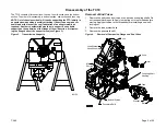
Before beginning the disassembly process, drain the fluid from the power take-off by removing the drain plug. Note that these instructions apply for out of
chassis overhaul of the unit.
Propeller Shaft Disconnect and Accessory Removal
Propeller Shaft Disconnect
Disconnect the propeller shafts.
Electrical Connections
Disconnect the tachometer cable, shift wiring and electric shift override
linkage.
Shift Unit
Remove the pneumatic or electric shift unit from the power take-off by
removing the two hex nuts and washers. Note that the adjusting screw
retaining springs are exposed when the shift unit is removed.
Eclipse ES CAFSystem
t
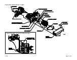
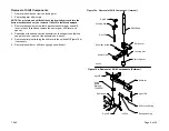
Removal from Power Take-Off (See Figure 1)
To remove the Eclipse ES CAFSystem from the PTO, perform the follow
ing steps:
1.
Support the Eclipse ES unit with a lifting strap placed under the air
compressor. Two other eyeloops are also provided for lifting (see
Figure 1).
2.
Remove all electrical and air connections.
3.
Remove the Polychain cover assembly by unscrewing the ten (10) hex
hd screws.
4.
Remove the nylon tube from the air clutch assembly.
5.
Loosen the 1-29/32" hex screw on the idler sprocket assembly. This
releases the idler sprocket assembly for adjustment.
6.
Loosen tension on the Polychain by turning the Polychain tension
screw, counter clockwise.
7.
Remove the Polychain from the air clutch assembly, driven sprocket
and idler sprocket.
8.
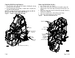
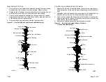
Loosen the set screw that holds the air clutch assembly to the PTO
driven shaft. (See Figure 2).
9.
Remove the hex head screw that attaches the air clutch assembly to
the anti-rotation bracket (leave grommet attached to anti-rotation
bracket).
10. Remove the air clutch assembly from the PTO.
11. Remove the five (5) hex hd screws that attach the Eclipse ES unit to
transmission.
12. Remove the compressor bracket that supports the Eclipse ES unit to
the PTO.
13. Lift the unit off the PTO.


