OPERATOR’S MANUAL
For technical assistance or the Water Maze Dealer nearest you, call (800) 535-0941 or
(360) 833-2333 or consult our web page at www.wmaze.com
■
CLP-5023
CLP-7023
CLP-7033
CLP
Page 1: ...OPERATOR S MANUAL For technical assistance or the Water Maze Dealer nearest you call 800 535 0941 or 360 833 2333 or consult our web page at www wmaze com CLP 5023 CLP 7023 CLP 7033 CLP...
Page 2: ...enerator Two Tube View CLP 5023 23 Ozone Generator Four Tube View CLP 7023 7033 24 Chemical Maintenance Program 25 Daily Chemical Maintenance 26 Centrifugal Pump 26 Pump Operation 26 Pump Manitenance...
Page 3: ...Sump Pump 5 23486 CLP 5023 47 48 Little Giant Submersible Sump Pump 23484 5 23485 CLP 7023 7033 49 50 Ebara Sump Pump 51 Transfer Pump Breakdown 5 2363 CLP 5023 52 Transfer Pump Breakdown 5 2365 CLP 7...
Page 4: ...l Number ______________________________ Serial Number ______________________________ Date of Purchase ____________________________ The model and serial numbers will be found on a decal attached to the...
Page 5: ...und system before connecting to the power supply WARNING Wire the system for correct voltage See Electrical section of this manual and motor nameplate WARNING Meet the National Electrical Code and loc...
Page 6: ...control box It is recommended that a ground fault circuit interrupter be installed in the circuit breaker for the CLP NOTE Electrician needs to locate where the power supply will enter the electrical...
Page 7: ...TOR S MANUAL 7 96 6294 Revised 7 04 CLP INSTALLATION VIEW FS 1 FS 2 Inlet Line Sump Pump Sump Pit Sump Pump Installation 3 Phase FS 7 FS 1 FS 2 Inlet Line Sump Pump Sump Pit Sump Pump Installation Sin...
Page 8: ...OPERATOR S MANUAL 96 6294 Revised 7 04 CLP ELECTRICAL INSTALLATION VIEW ALL MODELS Electrical Grounding Bolt For Detail See Ozone Generator Illus Electrical Power Supply Provided By Qualified Electri...
Page 9: ...CLP OPERATOR S MANUAL 9 96 6294 Revised 7 04 WATER PANEL INSTALLATION VIEW SV1 SV2 Water Panel All Models To Permitted Sewer or Storage Tank To Pressure Washer Fresh Water Supply...
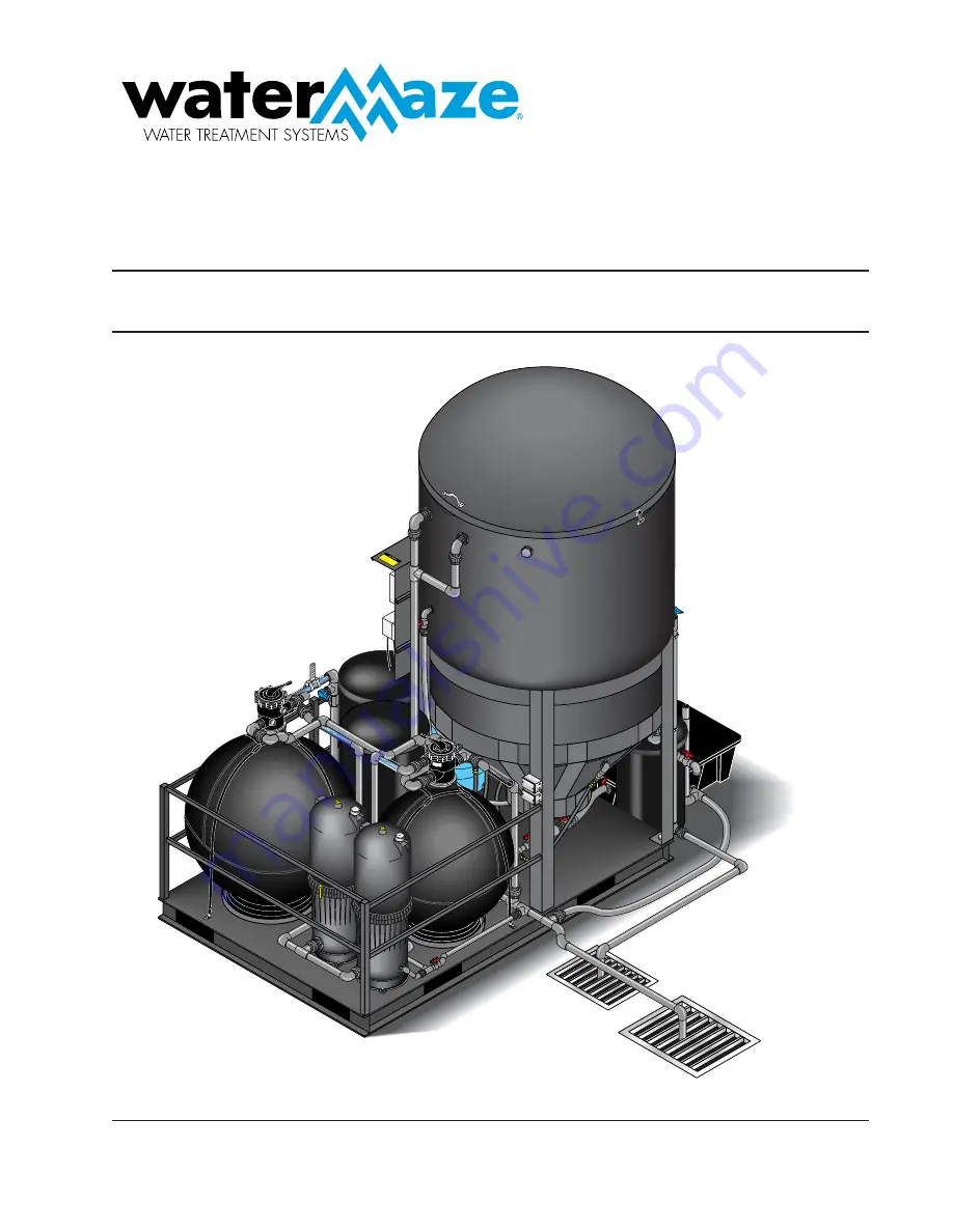
Page 10: ...r from the sump and sends it to the CLP 1 3 HP for CLP 5023 The solids settle in the bottom of the cone The oil and grease are separated out by the coa lescing cones The 3 4 HP Ozone pump takes water...
Page 11: ...vate an alarm to indicate that the filters are obstructed and need to be backwashed This switch is located between the Multi Media Filter and the Filter Pump Float Override Switch The Float Override S...
Page 12: ...he pump is put into operation the pressure switch may need to be adjusted The 3 4 hp pump and the 2 hp pump are normally set at 20 psi ON and 40 psi OFF Check to assure the oil skimmer is adjusted pro...
Page 13: ...n other words the amount of ozone being injected into the water 1 With the pump running disconnect the tubing from the ozone check valve and connect the tubing to the bottom fitting on the gauge This...
Page 14: ...ised 7 04 Oil Skimmer Funnel pH Pump Pressure Switch Valve 1 Valve 14 Valve 13 Valve 3 Valve 12 Valve 4 Inlet Flow Meter Pressure Switch PS 2 Filter Flow Meter CLP OPERATION VIEW CLP 5023 ORP pH Brack...
Page 15: ...ATOR S MANUAL 15 96 6294 Revised 7 04 Valve 14 Oil Skimmer Funnel pH Pump Pressure Switch Valve 12 Valve 13 CLP OPERATION VIEW CLP 7023 7033 ORP pH Bracket Filter Flow Meter Valve 16 Valve 5 Valve 15...
Page 16: ...lement off the Dirt Catcher assembly b Clean cartridge see section on Cleaning Car tridges Reinstalling Cartridges 1 Flush and drain any dirt or debris from the bottom of the filter tank 2 Carefully r...
Page 17: ...at make it ideal for water treatment Ozone s Characteristics Ozone is well suited for water treatment and it s unique characteristics are described below Ozone works up to 3 000 times faster than chlo...
Page 18: ...g from around the end of the lamp by turning it counterclockwise and remove it Re move the lamp by grabbing the rubber bushing around the end of the lamp and pulling it straight out Remove OZONE GENER...
Page 19: ...eaction Chamber Feed Gas Inlet to Reaction Chamber Transformer Mother Board Variable Ozone Outlet Control SCFH Gauge Attached to External Air Prep Access Loop Check Valve Replacement Part 2 30159 To M...
Page 20: ...t tom of the CD10 AD described on next page Below the ten ozone output LED s are seven colored rectangu lar LED s which indicate the unit s operational status as follows POWER Green LED indicates that...
Page 21: ...ted daily to insure water is not flowing back into the ozone generator Check valves should be replaced yearly Note The only time it is possible for water to flow back toward the ozone generator is dur...
Page 22: ...inside of the stainless steel reaction chamber with a wire brush as necessary then wipe with isopropyl alcohol 8 Be sure all solvents have evaporated prior to re assembly Re Installation of the Diele...
Page 23: ...trol Switch Power In B W B W Indicating Lights NOTE Green Indicating Light Operation Bright Continuous Light Indicates UV Light or Ballast Defective Dim Continuous Light Indicates Proper Operation LEG...
Page 24: ...mer RYW B B Control Switch BL BL BL BL B W G Power In Ground W B W B W B W B Indicating Lights Note Green Indicating Light Operation Bright Continuous Light Indicates UV Light of Ballast Defective Dim...
Page 25: ...NCE PROGRAM Owner Chemical Maintenance Program to Maintain Recycled Water Quality Daily monitoring and adjustment of Water Maze recycled waterchemistryisessential Ifnotmonitoredandcontrolled the recyc...
Page 26: ...he water is circulating from the sump through the CLP system and back to the catch basin Step 2 Using the test strips supplied measure A The pH B The total chlorine if using chlorine C The free chlori...
Page 27: ...Base Jumper Because most systems are dealing with a high pH situa tion the controller is factory set for acid feed If you re quire a base feed turn power off to entire system open plastic door on cont...
Page 28: ...t be kept clean and free from chemi cal deposits and contamination to function properly Af ter saturation in the waste stream the sensors may need to be cleaned on a weekly or monthly basis depending...
Page 29: ...ACTIVATE Make sure the AUTO feed light for ORP is on Check the ORP setpoint Check ORP relay fuse 5A slow blow marked F2 on control board pH FEEDER DOES NOT ACTIVATE Verify that the acid base feed jum...
Page 30: ...counterclockwise before tightening the pro cess connection When the sensitivity of the sensor has decreased or the response has slowed down the electrode needs cleaning If cleaning with hot water is n...
Page 31: ...press on this key moves the cursor or flash ing digit one place to the right is used to change the value of a se lected digit Each press on this key in creases the value by one unit The value can not...
Page 32: ...i t c e n n o c d e g a m a D s e l b a c e c a l p e R 1 5 E h g i h o o t 1 t u p n i f o e c n a d e p m I d e t c e n n o c s i d r o s n e s g n i r u s a e M s n o i t c e n n o c k c e h C s s...
Page 33: ...e s g n o r W m a r g o r p e R 6 1 E e m i t l a v r e t n i e c n a n e t n i a m r o f l l a C d e d e e c x e t e s e r p n i d e n i a t n i a m t o n m e t s y S d o i r e p e m i t e c n a n e...
Page 34: ...on Press YES to start calibration Note To start calibration with another solution press NO to cycle through the other options NO Rinse sensor Transfer to second buffer pH4 and press YES The display no...
Page 35: ...ement CFR 200 20 Micron 1 65 C9500 Element 200 Sq Ft 5 Micron 1 12 65 42 2993 05 R Dirt Catcher 150 St Ft 1 CARTRIDGE FILTER ASSEMBLY 2 9804 CLP 5023 3 4 6 8 17 1 ITEM PART NO DESCRIPTION QTY 13 2 010...
Page 36: ...3 16 x 3 8 x 3 32 1 5 65 9193 4182 R Pressure Gauge 0 60 1 4 CBM 1 6 65 42 3611 01 R Filter Cover 250 sq ft 1 7 65 47 0380 47 R O Ring 11 1 2 x 11 7 8 x 3 16 1 ITEM PART NO DESCRIPTION QTY 8 65 42 387...
Page 37: ...11175 1 8 65 31 0113 64 R004 Upper Pipe 1 1 2 x 4 1 2 PVC 160 1 9 65 88 1580 01 R Filter Basket 1 10 65 42 3516 01 R Laser 225 Standpipe Mfg Assy 1 11 65 42 3511 06 R Laser 225 Lateral Assy 8 12 65 94...
Page 38: ...14 3852 07 R Pin 1 3 65 14 3834 00 R Washer 1 4 65 14 3851 08 R Shim 2 5 65 39 2550 05 Cover 1 6 65 14 4354 01 R PLPH 10 14 x 1 4 7 65 47 0214 07 R O Ring 1 8 65 14 3833 01 R Washer 3 9 65 16 0262 05...
Page 39: ...9 65 88 1580 01 R Filter Basket 1 10 65 42 3518 09 R Laser 250 Standpipe Manf Assy 1 11 65 42 3517 00 R Laser 250 Lateral Assy 85 5322 08 8 12 65 9408 3730 R Laser 250 Tank Assembly 1 13 65 85 8533 00...
Page 40: ...3 65 85 5322 08 R000 Lateral TM26 1 65 42 2979 03 R000 Lateral TM31 1 65 42 2979 03 R000 Lateral TM36 1 4 65 42 1141 16 R000 Standpipe TM26 1 65 42 3500 31 R000 Standpipe TM31 1 65 42 3597 02 R000 Sta...
Page 41: ...62 07 R Eye Seal 1 2 1 HP Full Rate 1 18 65 05 3801 00 R Impeller 3 4 HP Full Rate 1 19 65 10 1502 09 Shaft Seal 1 SIZE INLET OUTLET RUNNING AMPS MAX PRESSURE MAX WATER TEMP 2 2 2 6 1 3 28 psi 120o F...
Page 42: ...e 1 18 65 05 3800 00 R Impeller 1 2 HP Full Rate 1 19 65 10 1502 09 Shaft Seal 1 SIZE INLET OUTLET RUNNING AMPS MAX PRESSURE MAX WATER TEMP 2 2 8 8 4 4 28 psi 120o F 50o C MODEL NO PART NO LISTING HP...
Page 43: ...PUMP CLP 5023 B C ITEM PART NO DESCRIPTION QTY 1 88 104000171 Washer 1 2 88 132000200 Base 1 3 88 118000340G Seal 1 4 88 137 000 001 5 5 Impeller 1 5 88 104000168 Washer 1 6 88 105000465 Nut 1 7 88 1...
Page 44: ...000171 Washer 1 2 88 132000200 Base 1 3 88 118000340G Seal 1 4 88 137 000 125 5 5 Impeller 1 5 88 104000168 Washer 1 6 88 105000465 Nut 1 7 88 130000170 Head 1 8 88 113000349 Motor 2 HP 230V 3 PH 460...
Page 45: ...N QTY 1 88 104000171 Washer 1 2 88 132000200 Base 1 3 88 118000340G Seal 1 4 88 137 000 126 5 5 Impeller 1 5 88 104000168 Washer 1 6 88 105000465 Nut 1 7 88 130000181 Head 1 8 88 1130000368 Motor Mara...
Page 46: ...46 CLP OPERATOR S MANUAL 96 6294 Revised 7 04 SCOT FILTER AND TRANSFER PUMP SPECIFICATIONS MODEL 5 2385 5 2386 5 2387 MODEL 5 23875...
Page 47: ...CLP OPERATOR S MANUAL 47 96 6294 Revised 7 04 LITTLE GIANT SUBMERSIBLE SUMP PUMP CLP 5023A 5 23486 230V...
Page 48: ...Seal Ring 5 187 x 099 1 18 84 948010 Bearing Flanged 2 19 84 979074 Rotor 1 20 84 108136 Washer Thrust 1 21 84 979077 Stator 1 22 84 106175 Volute 1 23 84 926031 Shaft Seal Assembly 1 24 84 106370 Imp...
Page 49: ...CLP OPERATOR S MANUAL 49 96 6294 Revised 7 04 LITTLE GIANT SUBMERSIBLE SUMP PUMP CLP 7023A CLP 7033A 5 23485 230V 10S PERFORMANCE CURVE...
Page 50: ...TS LIST ITEM PART NO DESCRIPTION QTY 20 84 111252 Impeller Assy 1 24 84 108101 Handle 1 25 84 947003 Plug Oil 2 26 84 106372 Lever Arm Assy 1 27 84 106377 Washer Plain Polyethylene 1 28 84 950940 Plug...
Page 51: ...MP CLP 5023 B C CLP 7023 B C CLP 7033 B C 5 2425 1 2 HP 230V 3PH 5 2426 1 2 HP 460V 3PH 87 360490501 Seal MODEL NO PART NO HP VOLTS PH SOLID SIZE RUNNING AMPS RPM DIMENSIONS H X L X W WEIGHT 50DWXU6 4...
Page 52: ...4 11 65 14 1302 23 R Hex Capscrew 3 8 16 x 2 3 4 PL 4 MODEL NO PART NO LISTING HP VOLTS PHASE 5CY 5 2363 CSA 1 2 115 230 1 MODEL NO PART NO SIZE INLET OUTLET RUNNING AMPS MAX PRESSURE MAX WATER TEMP...
Page 53: ...2 23 R Hex Capscrew 3 8 16 x 2 3 4 PL 4 MODEL NO PART NO LISTING HP VOLTS PHASE WEIGHT 7CY 5 2365 CSA 3 4 115 230 1 31 lbs MODEL NO PART NO SIZE INLET OUTLET RUNNING AMPS MAX PRESSURE MAX WATER TEMP 7...
Page 54: ...allons Per Minute 5CY 9102 0050 5 12 10 7 9 1 7 2 4 9 2 8 9 62 10 10 8 4 6 3 3 9 1 9 60 15 7 7 5 3 3 9 57 20 6 4 4 3 2 2 2 55 25 5 3 3 1 4 53 CY1 Discharge 1 1 4 Suction Discharge Pressure PSI Shutoff...
Page 55: ...R Mechanical Seal 12 65 02 1388 08 R Bracket 2 010056 Compression Fitting 1 1 2 2 13 65 14 3970 04 R PL Hex Bolt 10 24x1 1 4 6 required 14 65 14 3971 03 R PL Hex Nut 6 required 15 65 31 1609 06 R Plu...
Page 56: ...FS4 Line to Main Tank Ring Assembly Ozone Line to Main Tank For Detail See Water Panel Illus Ozone Line to Main Tank Filter Pump T1 T2 To Main Drain Line Ozone Pump 1 2 3 4 5 4 5 6 7 36 34 35 37 21 23...
Page 57: ...ve 1 S x S 2 23 2 01146 Union 1 S x S 4 24 2 0100191 Hanger Pipe 1 1 4 Click 3 25 2 01001321 Elbow 1 S x S 5 CLP 5023 PLUMBING BREAKDOWN ASSEMBLY PARTS LIST ITEM PART NO DESCRIPTION QTY 26 2 0100160 A...
Page 58: ...6 ORP Injector To Carbon Filter Line to Coalescing Tank 14 Flow Meter Pre Pressurized Surge Tank Gate Valve SV3 Line to Blowout Main Drain Line Line To Sump Pits Sludge Tub T2 T1 To Multi Media Filter...
Page 59: ...1 1 2 S x S 2 12 2 01002 Nipple Close 1 1 2 3 13 2 010057 Bulkhead 1 1 2 3 14 4 05010 Gauge Flowmeter 1 1 2 1 15 2 3035 Valve Gate PVC 1 1 2 S x S 1 16 2 0100201 Tee 1 1 2 S x S x S 5 17 2 0100158 Bu...
Page 60: ...n Line to Coalescing Tank To Transfer Pump T1 T2 5 Multi Media Filter Cartridge Filter Carbon Filter To Main Drain Line 5 Carbon Filter To Main Drain Line To Vertical Holding Tank 2 2 1 1 2 1 2 6 6 13...
Page 61: ...0100302 Adapter 1 1 2 S x MT 9 7 9 5005850 Bucket 26 Gal w Lid 1 8 2 0100154 Bushing 2 x 1 1 2 T x T 2 9 2 9814 Dial Valve Kit 2 10 30 8410 Strap 84 Filter 4 11 95 0710056 Filter Tab 4 12 65 9193 4182...
Page 62: ...g Tank 1 For Detail See Control Panel Illus Ring Assembly Tank Lid 300 Gal Coalescing Tank Oil Skimmer Funnel 16 Line to Flow Meter Coalescing Cones T1 T2 Oil Collection Barrel Multi Media Filter Carb...
Page 63: ...e Supporting Coalescing CLP 5000 1 9 500596 Cone CLP 5000 Coalescing w Slot w o Hole 1 9 500597 Cone CLP 5000 Coalescing w o Slot w Hole 1 12 4 02190006 Hose 2 Gray Conduit 12 ft ITEM PART NO DESCRIPT...
Page 64: ...in Tank Ozone Line to Main Tank 8 24 20 31 28 26 27 40 To Manifold Assembly 39 Ozone Pump Mazzi Injector 42 43 30 29 32 34 33 To Vertical Holding Tank 2 T1 To Cartridge Filters 35 38 To Media Filters...
Page 65: ...46 Union 1 S x S 3 ITEM PART NO DESCRIPTION QTY 27 2 01001321 Elbow 1 S x S PVC 80 2 28 2 0100160 Adapter 1 MT x Slip 1 29 2 0100156 Bushing 1 1 4 x 1 MT x FT 1 30 2 01003 Nipple 1 Close 2 31 2 301 Va...
Page 66: ...S3 Vertical Holding Tank 1 32 Pressure Switch 1PF ORP Injector Pre Pressurized Surge Tank 24 Gate Valve Line To Tank Blowout For Detail See 5 Port Manifold Illus SV3 20 Flow Meter Lines To Main Tank R...
Page 67: ...2 x 1 8 Brass 1 13 2 0100159 Bushing 1 2 x 1 4 PVC 80 1 14 2 0100430 Union 1 1 2 S x S 1 5 2 15 2 0100132 Elbow 1 1 2 S x T 90 3 16 2 01002 Nipple 1 1 2 Close 3 17 2 010057 Bulkhead 1 1 2 3 ITEM PART...
Page 68: ...Coalescing Tank 17 1 To Filter Pump Assembly 1 2 1 2 3 1 3 19 18 16 Multi Media Filter 2 2 6 4 T1 T2 5 2 2 2 3 6 14 7 6 5 4 2 5 6 10 8 9 9 11 Cartridge Filter 8 9 10 11 13 12 14 11 To Main Drain Assem...
Page 69: ...2 010018511 Bushing Reducer 2 x 1 T x T 2 9 2 01001321 Elbow 1 S x S 90 3 10 2 01001301 Elbow 1 S x S 45 2 11 2 01146 Union 1 S x S PVC 80 3 12 2 0100205 Tee 1 S x S x S PVC 80 1 13 2 3092 Valve 1 Sch...
Page 70: ...ntrol Panel Illus 20 To Vertical Holding Tank 1 600 Gal Coalescing Tank ORP Sensor Bracket T1 T2 7 Junction Boxes 6 Line To Main Tank Drain Multi Media Filter 26 16 27 15 12 11 12 14 10 29 13 14 13 18...
Page 71: ...kimmer 1 11 2 01005 Nipple 1 1 2 x 6 PVC 1 12 2 010057 Bulkhead 1 1 2 Polypro 3 13 2 0100302 Adapter 1 1 2 Slip x MPT 2 14 2 0100430 Union 1 1 2 S x S 2 15 2 30096 Valve Ball Check 1 2 1 16 2 0100201...
Page 72: ...ing Tank 2 T2 Main Drain Assembly Multi Media Filter Filter Pump 16 Filter Flow Meter To Multimedia Filter 15 15 PSI Pressure Switch To Vertical Holding Tank 1 To Cartridge Filters To Carbon Filter Ca...
Page 73: ...S x S PVC 80 1 24 2 0100311 Adapter 1 x 3 4 S x FIPT 1 25 2 01001321 Elbow 1 S x S 90 5 26 2 01001325 Elbow 1 T x T PVC 80 90 1 ITEM PART NO DESCRIPTION QTY 27 2 010056 Fitting Compression 1 1 2 2 28...
Page 74: ...o Detail See 5 Port Manifold Illus Line To Main Tank Bottom Cone SV3 Surge Tank Main Tank Drain T2 T1 To Drain Line Assembly Port Carbon Filter Line To Sump Pit Multi Media Filter Cartridge Filter Car...
Page 75: ...x 1 8 1 13 2 0100159 Bushing 1 2 x 1 4 PVC 80 1 14 2 0100430 Union 1 1 2 S x S 1 5 2 15 2 0100132 Elbow 1 5 S x T 90 3 16 2 01002 Nipple 1 5 Close 3 ITEM PART NO DESCRIPTION QTY 17 2 010057 Bulkhead...
Page 76: ...alescing Tank To Transfer Pump Assembly 16 Multi Media Filter 15 Carbon Filter To Main Drain Assembly 14 Cartridge Filter To Main Drain Assembly 14 Cartridge Filter 4 1 4 4 2 2 1 1 3 4 7 6 4 5 6 7 4 1...
Page 77: ...x S 4 8 2 010018511 Bushing Reducer 2 x 1 2 9 2 01001321 Elbow 90 S x S 1 3 10 2 01001301 Elbow 1 S x S 45 2 11 2 01146 Union 1 S x S PVC 80 3 12 2 0100205 Tee 1 S x S x S PVC 80 1 13 2 3092 Valve 1 S...
Page 78: ...24 ORP Sensor Bracket To Vertical Holding Tank 1 For Detail See Control Panel Illus Coalescing Cones Surge Tank 7 Junction Boxes 6 Line To Main Tank Drain T2 T1 Carbon Filter Cartridge Filter Multi M...
Page 79: ...010057 Bulkhead 1 1 2 Polypro 2 13 2 0100302 Adapter 1 1 2 Slip x MPT 2 14 2 0100430 Union 1 1 2 S x S 2 15 2 30096 Valve Ball Check 1 2 1 ITEM PART NO DESCRIPTION QTY 16 2 0100201 Tee S x S x S 1 1...
Page 80: ...4 6 6 12 10 11 9 7 To Transfer Pump 9 8 3 6 6 3 4 10 11 To Water Panel CLP 5023 7023 4 Port Manifold Assembly To Water Panel 12 14 19 4 5 9 Line to Pre Pressurized Surge Tank 6 5 4 13 17 18 15 16 12 4...
Page 81: ...3 4 x 3 4 JIC 2 6 2 0100311 Adapter 1 x 3 4 S x T 6 7 2 01003 Nipple 1 Close PVC 80 1 8 2 01001327 Elbow 1 Slip x Fipt PVC 80 90 1 9 2 0100205 Tee 1 S x S x S PVC 80 5 10 2 0100191 Pipe Hanger 1 1 4...
Page 82: ...Main Tank Drain Assembly 17 12 16 15 14 13 5 4 6 6 9 5 4 3 Main Drain Line 4 12 5 5 5 6 6 11 10 9 9 8 4 7 4 4 4 12 CLP 7033 5 Port Manifold Assembly MANIFOLD BREAKDOWN CLP 7033 For Detail See Water Pa...
Page 83: ...6 2 0100311 Adapter 1 x 3 4 S x T 5 7 2 01003 Nipple 1 PVC 80 Close 1 8 2 01001327 Elbow 1 Slip x FIPT 1 9 2 0100205 Tee 1 S x S x S PVC 80 5 10 2 0100191 Pipe Hanger 1 1 4 2 11 2 01001321 Elbow 1 S...
Page 84: ...84 CLP OPERATOR S MANUAL 96 6294 Revised 7 04 OZONE GENERATOR BREAKDOWN 4 TUBE 21 6 6 9 23 10 1 4 11 19 12 11 17 13 14 25 16 3 22 8 2 20 18 24 7 15 5...
Page 85: ...Poly 2 12 2 01133 Tee 3 8 Poly 1 13 2 0141 Bushing 1 2 Snap 1 14 4 02080002 Tubing 3 8 x 1 2 Vinyl 6 ft ITEM PART NO DESCRIPTION QTY 15 6 0101 Cord Service SEO 16 3 8 ft 16 6 020251 Switch Curvette 12...
Page 86: ...86 CLP OPERATOR S MANUAL 96 6294 Revised 7 04 CONTROL PANEL BREAKDOWN 230V MODELS 1 11 13 12 9 11 10 8 4 3 2 22 19 17 21 21 5 6 7 20 14 15 23 16 16 25 24 18 For Detail See Ozone Generator Illus 26...
Page 87: ...0V 500 KVA CLP 7023C CLP 7033C 1 6 6023 Transformer 230 400V 115 230V 100 KVA CLP 7033K 1 CONTROL PANEL BREAKDOWN PARTS LIST ITEM PART NO DESCRIPTION QTY 13 6 02299 Fuse ATMR 2 Amp 120V Secondary 1 14...
Page 88: ...294 Revised 7 04 WATER PANEL BREAKDOWN CLP 5023 7023 1 14 5 12 5 7 Valve 8 8 6 4 4 3 2 6 9 6 6 5 11 10 6 6 13 13 7 10 5 11 Valve 6 Valve 7 Valve 9 To Manifold Assembly To Manifold Assembly To Holding...
Page 89: ...94 Revised 7 04 WATER PANEL BREAKDOWN CLP 7033 1 2 14A Water Panel Front View 3 4 10 5 7 Valve 8 11 10 4 8 6 5 12 5 9 6 6 10 5 13 12 13 To Manifold Assembly To Manifold Assembly 6 To Holding Tank 2 4...
Page 90: ...educer 4 6 2 1105 Swivel 3 4 SAE Female Push on 7033 6 5023 7023 8 7 6 140166 Solenoid Valve 24V PVC 2 8 2 1042 Tee 1 2 Street 1 9 2 10621 Elbow 3 4 JIC x 3 4 SAE 90 Elbow 1 10 2 1062 Elbow 1 2 JIC x...
Page 91: ...ker box Float in sump in down position Add water to pump Debris in sump impeller Unplug pump and remove from container Flow valve closed Open valve Dirt lodged in control valve Clean as needed Frozen...
Page 92: ...erly Check valve stuck or plugged Transfer Pump Remove check valve and inspect for proper operation Lift too high for pump Check rating table Inlet to impeller plugged Pull pump and clean Low line vol...
Page 93: ...ently See section on Pump Cycles Continually on previous page Defective float switch Disconnect switch check with ohmmeter MOTOR RUNS BUT NO WATER IS DELIVERED Pump in a new installation did not pick...
Page 94: ...motor or capacitor Contact the nearest distributor Hole in the intake cover is blocked Clean the hole No return valve blocked Clean the valve and check its operation THE PUMP WORKS AT A LOW FLOW RATE...
Page 95: ...ed Open valve Cartridge filter clogged Clean Pump impeller vanes clogged Cleaning with a stiff wire through the pump inlet opening will usually work Alternate would be to disassemble and clean Air lea...
Page 96: ...in manual ON position Turn solenoid clockwise to OFF position Diaphragm bleed hole blocked Use Manual Flush Mode Turn water supply OFF and immediately back ON to clear blockage If still blocked turn o...
Page 97: ...hermal cracks Check to insure seal chamber is full of liquid before starting pump On high temperature application insure proper flushing at seal faces CARBON WASHER SCORED AND GROOVED Dirty system Hav...
Page 98: ...d n a y r t s i m e h c r e t a w k c e h C r e l l o r t n o c X k n a t n o i t c e l l o c n i l i o f o l e v e l k c e h C X l e v e l r e p o r p r o f r e m m i k s l i o n o t n e m t s u j d...
Page 99: ...100 from lack of refrigeration after received and stored WHATYOU MUST DO TO OBTAIN WARRANTY SERVICE While not required for warranty service we request that you register your WATER MAZE Product by retu...
Page 100: ...Form 96 6294 Revised 7 04 Printed in U S A...