


WaterFurnace works continually to improve its products. As a result, the design and specifi cations of each product at the time of order may be changed without notice. Please contact WaterFurnace at 1-888-929-2837 for latest design and
specifi cations. Purchaser’s approval of this data set signifi es that the equipment is acceptable under the provisions of the job specifi cation. Statements and other information contained herein are not express warranties and do not form the
basis of any bargain between the parties, but are merely WaterFurnace’s opinion or commendation of its products. The latest version of this document is available at www.waterfurnace.com.
Contractor: P.O.:
Engineer:
Project Name:
Unit Tag:
SD2552WNB 09/16
30
Page _____ of _____
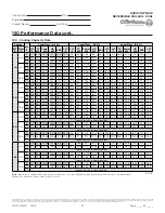
ENVISION
2
NKW
REVERSIBLE CHILLER - 50Hz
PART 3 - EXECUTION
CHILLER INSTALLATION
Install chillers on support structure indicated.
Equipment Mounting:
Install chiller on concrete bases using
elastomeric pads. Comply with requirements for vibration
isolation devices specified in Division 23 Section "Vibration
and Seismic Controls for HVAC Piping and Equipment."
•
Minimum Deflection: 12mm.
•
Install dowel rods to connect concrete base to
concrete floor. Unless otherwise indicated, install
dowel rods on 450mm centers around the full
perimeter of concrete base.
•
For supported equipment, install epoxy-coated anchor
bolts that extend through concrete base and anchor
into structural concrete floor.
•
Place and secure anchorage devices. Use setting
drawings, templates, diagrams, instructions, and
directions furnished with items to be embedded.
•
Install anchor bolts to elevations required for proper
attachment to supported equipment.
Equipment Mounting:
Install chiller using elastomeric pads.
Comply with requirements for vibration isolation devices
specified in Division 23 Section "Vibration and Seismic
Controls for HVAC Piping and Equipment."
Equipment Mounting:
Install chiller on concrete bases.
Comply with requirements for concrete base specified
by contractor.
•
Install dowel rods to connect concrete base to
concrete floor. Unless otherwise indicated, install
dowel rods on 450mm centers around the full
perimeter of concrete base.
•
For supported equipment, install epoxy-coated anchor
bolts that extend through concrete base and anchor
into structural concrete floor.
•
Place and secure anchorage devices. Use setting
drawings, templates, diagrams, instructions, and
directions furnished with items to be embedded.
•
Install anchor bolts to elevations required for proper
attachment to supported equipment.
Maintain manufacturer's recommended clearances for
service and maintenance.
Charge chiller with refrigerant and fill with oil if not
factory installed.
Install separate devices furnished by manufacturer and not
factory installed.
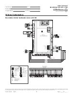
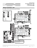
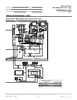
CONNECTIONS
Comply with requirements for piping specified in Division
23 Section "Hydronic Piping." Drawings indicate general
arrangement of piping, fittings, and specialties.
Install piping adjacent to chiller to allow service
and maintenance.
Evaporator Fluid Connections:
Connect to evaporator inlet
with shutoff valve, strainer, flexible connector, thermometer,
and plugged tee with pressure gage. Connect to evaporator
outlet with shutoff valve, balancing valve, flexible connector,
flow switch, thermometer, plugged tee with shutoff valve
and pressure gage, flow meter, and drain connection with
valve. Make connections to chiller with a flange.
Condenser Fluid Connections:
Connect to condenser inlet
with shutoff valve, strainer, flexible connector, thermometer,
and plugged tee with pressure gage. Connect to condenser
outlet with shutoff valve, balancing valve, flexible connector,
flow switch, thermometer, plugged tee with shutoff valve
and pressure gage, flow meter, and drain connection with
valve. Make connections to chiller with a flange.
Connect each chiller drain connection with a union and
drain pipe, and extend pipe, full size of connection, to floor
drain. Provide a shutoff valve at each connection.
STARTUP SERVICE
Engage a factory-authorized service representative to
perform startup service.
•
Complete installation and startup checks according to
manufacturer's written instructions.
•
Verify that refrigerant charge is sufficient and chiller
has been leak tested.
•
Verify that pumps are installed and functional.
•
Verify that thermometers and gages are installed.
•
Operate chiller for run-in period.
•
Check bearing lubrication and oil levels.
•
For chillers installed indoors, verify that refrigerant
pressure relief device is vented outdoors.
•
Verify proper motor rotation.
•
Verify static deflection of vibration isolators, including
deflection during chiller startup and shutdown.
•
Verify and record performance of fluid flow and low-
temperature interlocks for evaporator and condenser.
•
Verify and record performance of chiller
protection devices.
•
Test and adjust controls and safeties. Replace
damaged or malfunctioning controls and equipment.
Inspect field-assembled components, equipment
installation, and piping and electrical connections for
proper assembly, installation, and connection.
Prepare test and inspection startup reports.


