Water Furnace 502W12 Installation Manual Download Page 9

9

5 SERIES 502W12 INSTALLATION MANUAL

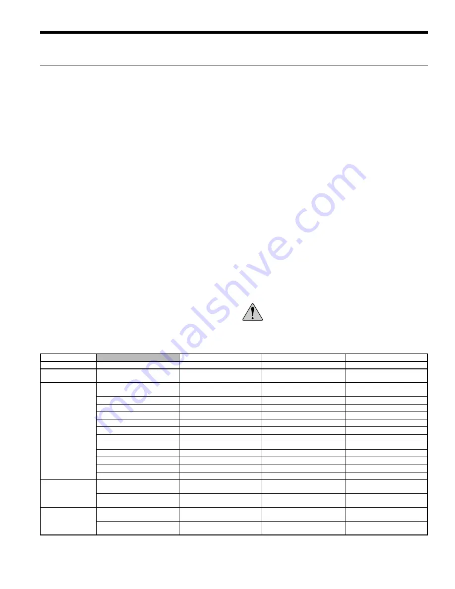
The following table outlines the water quality guidelines for unit 
heat exchangers.  If these conditions are exceeded, a secondary 
heat exchanger is required. Failure to supply a secondary heat 
exchanger where needed will result in a warranty exclusion for 
primary heat exchanger corrosion or failure.

Strainers

These units must have properly sized strainers upstream of 
both brazed plate heat exchangers to protect them against 
particles in the fluid. Failure to install proper stainers and 
perform regular service can result in serious damage to the 
unit, and cause degraded performance, reduced operating 
life and failed compressors. Improper installation of the unit 
(which includes not having proper strainers to protect the 
heat exchangers) can also result in voiding the warranty.  

Field supplied strainers with 420-840 microns are 
recommended, with 500 microns being the optimum choice. 
The strainers selected should have a mesh open area of at 
least 39 cm

2

 for each unit being serviced by the strainer. Using 

strainers with a smaller amount of open area will result in the 
need for more frequent cleaning.

Strainers should be selected on the basis of acceptable 
pressure drop, and not on pipe diameter. The strainers 
selected should have a pressure drop at the nominal flow rate 
of the units; low enough to be within the pumping capacity of 
the pump being used.

WARNING: Must have intermediate heat 
exchanger when used in pool applications.

General

Reversible chiller systems may be successfully applied in a 
wide range of commercial and industrial applications. It is the 
responsibility of the system designer and installing contractor 
to ensure that acceptable water quality is present and that all 
applicable codes have been met in these installations.

Water Treatment

Do not use untreated or improperly treated water. Equipment 
damage may occur. The use of improperly treated or 
untreated water in this equipment may result in scaling, 
erosion, corrosion, algae or slime. The services of a qualified 
water treatment specialist should be engaged to determine 
what treatment, if any, is required. The product warranty 
specifically excludes liability for corrosion,  erosion or 
deterioration of equipment.

The heat exchangers in the units are 316 stainless steel plates 
with copper brazing. The water piping in the heat exchanger 
is steel. There may be other materials in the building’s piping 
system that the designer may need to take into consideration 
when deciding the parameters of the water quality.

If an antifreeze or water treatment solution is to be used, the 
designer should confirm it does not have a detrimental effect 
on the materials in the system.

Contaminated Water

In applications where the water quality cannot be held to 
prescribed limits, the use of a secondary or intermediate heat 
exchanger is recommended to separate the unit from the 
contaminated water.

Water Quality

Water Quality Guidelines

Material

Copper

90/10 Cupronickel

316 Stainless Steel

pH

Acidity/Alkalinity

7 - 9

7 - 9

7 - 9

Scaling

Calcium and

Magnesium Carbonate

(Total Hardness)

less than 350 ppm

(Total Hardness)

less than 350 ppm

(Total Hardness)

less than 350 ppm

Corrosion

Hydrogen Sulfide

Less than 0.5 ppm (rotten egg 

smell appears at 0.5 ppm)

10 - 50 ppm

Less than 1 ppm

Sulfates

Less than 125 ppm

Less than 125 ppm

Less than 200 ppm

Chlorine

Less than 0.5 ppm

Less than 0.5 ppm

Less than 0.5 ppm

Chlorides

Less than 20 ppm

Less than 125 ppm

Less than 300 ppm

Carbon Dioxide

Less than 50 ppm

10 - 50 ppm

10 - 50 ppm

Ammonia

Less than 2 ppm

Less than 2 ppm

Less than 20 ppm

Ammonia Chloride

Less than 0.5 ppm

Less than 0.5 ppm

Less than 0.5 ppm

Ammonia Nitrate

Less than 0.5 ppm

Less than 0.5 ppm

Less than 0.5 ppm

Ammonia Hydroxide

Less than 0.5 ppm

Less than 0.5 ppm

Less than 0.5 ppm

Ammonia Sulfate

Less than 0.5 ppm

Less than 0.5 ppm

Less than 0.5 ppm

Total Dissolved Solids (TDS)

Less than 1000 ppm

1000 - 1500 ppm

1000 - 1500 ppm

LSI Index

+0.5 to -0.5

+0.5 to -0.5

+0.5 to -0.5

Iron Fouling

(Biological Growth)

Iron, FE

2

+ (Ferrous)

Bacterial Iron Potential

< 0.2 ppm

< 0.2 ppm

< 0.2 ppm

Iron Oxide

Less than 1 ppm, above this 

level deposition will occur

Less than 1 ppm, above this 

level deposition will occur

Less than 1 ppm, above this 

level deposition will occur

Erosion

Suspended Solids

Less than 10 ppm and filtered 

for max. of 600 micron size

Less than 10 ppm and filtered 

for max. of 600 micron size

Less than 10 ppm and filtered 

for max. of 600 micron size

Threshold Velocity

(Fresh Water)

< 1.8 m/sec

< 1.8 m/sec

< 1.8 m/sec

NOTES: 

Grains = ppm divided by 17
mg/L is equivalent to ppm

2/22/12

Summary of Contents for 502W12

Page 1: ...er Piping Connections Electrical Data Microprocessor Control Startup Procedures Preventive Maintenance 5 Series 502W12 Installation Manual C US 5 Serie ll l High Temp Hydronic Geothermal Heat Pump R 1...

Page 2: ......

Page 3: ...Control Setup 17 Control Features 18 Sequence of Operation 20 Inputs and Outputs Configuration 21 Unit Display and Interface 21 Reference Calculations 24 Legend 24 Unit Startup 24 Operating Parameter...

Page 4: ...10 0 11 A 12 B 13 14 SS 15 A Model NHW 5 Series High Temp Hydronic Heat Pump Capacity 084 Dual Compressor 84 MBtu h Operation H Heating Only R Reversible Voltage 1 208 230 60 1 Controls 8 FX10 std no...

Page 5: ...ier should make the proper notation on delivery receipt acknowledging the damage Units are to be stored in a location that provides adequate protection from dirt debris and moisture WARNING To avoid e...

Page 6: ...steel hose clamps CK5L XLS 1 1 4 in rubber hose kit includes all the same items from CK5L XL plus 1 1 4 in 20 mesh bronze strainer WARNING All field installed piping and piping connections must be ra...

Page 7: ...s Under this scenario the evaporating temperature can fall outside of the compressor operating window To allow the system to operate correctly restricting the source side flow when the evaporating te...

Page 8: ...Air Separator Back Flow Preventer Pressure Relief Valve GEO STORAGE TANK 3 Way Valves Y Strainer required to prevent damage from fouling Hose Kit Pressure Reduction Pressure Reduction Hose Kit P T Po...

Page 9: ...sion erosion or deterioration of equipment The heat exchangers in the units are 316 stainless steel plates with copper brazing The water piping in the heat exchanger is steel There may be other materi...

Page 10: ...6 A 473 2 B7 B 03 AE7B1632 1 B 0 F B7 2 A C 13 AB 2 2 B7 E B3 7 3A 7 G A3 D713 113AA 2 A C 13 1 B 0 F B3 B3 A3 D713 113AA B7 E D B 53 9 19 CB 7 3 D B 53 9 19 CBA E D B 53 9 19 CB 1 B 0 F B7 1 B 0 F A6...

Page 11: ...pressor 2 each Scroll Factory Charge R 134a oz kg 76 2 16 Load Water Connection FPT in 1 25 Source Water Connection FPT in 1 25 Weight Operating lb kg 420 190 Weight Packaged lb kg 415 188 2 14 12 HAC...

Page 12: ...Red 36 T Yellow Blue 37 Yellow Blue 38 Tan Black 84 Tan Black 85 S WCT Circuit A L WCT Circuit A S WCT Circuit B L WCT Circuit B LLT Green Yellow 23 Yellow 21 Black White 22 Black 64A 2 3 1 PB2 Black...

Page 13: ...Black F20 Timer delay on close Red 104 Yellow 102 Black 30 97P841 01 03 15 12 Ground Legend CC Compressor Contactor CS Current Switch ELT Entering Load Temp ES Emergency Shutdown EST Entering Source T...

Page 14: ...Circuit A S WCT Circuit B L WCT Circuit B LLT Green Yellow 23 Yellow 21 Black White 22 Black 64A 2 3 1 PB2 Black 54 Red 55 Gray 56 Pink 58 Brown 57 Gray 59 6 15 7 16 9 8 17 14 5 18 13 4 1 3 12 10 11 2...

Page 15: ...ck F18 Black F19 Black F20 Timer delay on close Black 30 Yellow 102 97P841 02 03 15 12 Ground Legend CC Compressor Contactor CS Current Switch ELT Entering Load Temp ES Emergency Shutdown EST Entering...

Page 16: ...6 Com DI6 DI5 DI4 DI3 DI2 DI1 9VDC 20 19 18 17 16 15 14 13 12 11 10 9 8 7 6 5 4 3 2 1 D09 D08 D07 D0 6 D05 D04 D03 D02 D01 J8 J2 J10 J9 J7 NOTE 7 A21 A12 A25 A22 A32 A31 A35 A23 A13 A11 A15 A14 A24 A3...

Page 17: ...ed wiring Terminals in the unit are not designed for other types of conductors WARNING All wiring must comply with local and state codes Disconnect the power supply before beginning to wire to prevent...

Page 18: ...4 The accessory output will be energized 90 seconds prior to the lead compressor output being energized When the lead compressor output is turned off the accessory output will be deactivated immediate...

Page 19: ...to operate so that the refrigerant temperature may eventually be at the threshold of the freeze detection setpoint NOTE This Lockout produces a Pre Freeze detection error on the MUI display Capacity...

Page 20: ...and the fixed compressor start delay timer has been satisfied When heating is no longer required the compressor will be turned off immediately after the compressor minimum on delay has been satisfied...

Page 21: ...sion Card Input Name Input Output Name Output Entering Source Water Temperature AI 1 Unused DO 1 Leaving Source Water Temperature 1 AI 2 Unused DO 2 Current Switch 1 Compressor 1 AI 3 Unused DO 3 Curr...

Page 22: ...1 30 0 F Load Frz2 30 0 F Src Frz Setpt 30 0 F LD Frz Setpt 30 0 F Temp Settings Unit of Measure F Settings Water to Water PRODCWWE 08B MM DD YY Unit Display and Interface cont Maintenance Y1 Input Au...

Page 23: ...point LD FP 1 Sensor Bad The sensor for load freeze detection on compressor circuit 1 is unreliable or is not reading Source Flow Source Flow Switch is Not Closed The source flow switch must be closed...

Page 24: ...Flow switches are installed and ready Freeze detection setpoints have been set in the microprocessor WARNING Verify ALL water controls are open and allow water flow PRIOR to engaging the compressor Fa...

Page 25: ...ions with 25 gpm for the load and source 2 14 12 Cooling Mode Entering Load Temp F Entering Source Temp F Suction Pressure psig Discharge Pressure psig Superheat F Subcooling F 50 30 15 25 28 50 18 26...

Page 26: ...nding 084 1 33 ohms 0 38 ohms NOTE Tolerance 7 2 14 12 Compressor Resistance Model Source gpm Load gpm EST F Heat Of Extraction HE Heat of Rejection HR 60 F 80 F 100 F 120 F 140 F 30 F 50 F 70 F 90 F...

Page 27: ...______PSI ______SAT F ______ F ______ F Liquid Line NOTE Do not attach refrigerant gauges unless a problem is suspected Suction Discharge Compressor RV Braze Plate Braze Plate FD ______PSI ______SAT F...

Page 28: ...______ AMPS n ______ AMPS Watts m x n x 0 85 o _____ WATTS o ______ WATTS o ______ WATTS 6 CAPACITY Cooling Capacity HR o x 3 413 p _____ btu hr Heating Capacity HE o x 3 413 p _____ btu hr 7 EFFICIE...

Page 29: ...a bypass of refrigerant If the unit will not heat check the reversing valve coil If the unit operation is noisy 1 Check compressor for loosened mounting bolts Make sure compressor is floating free on...

Page 30: ...Pressure Switch 35P512 01 Water Temperature Sensor 12P529 04 Freeze Detection Sensor 12S529 01 Electrical Compressor Contactor 13P004A03 Transformer 15P501B01 Connection Block Small 12P503 06 Connect...

Page 31: ...502W12 INSTALLATION MANUAL Revision Guide Pages Description Date By 18 Updated Field Wiring and Control Setup 25 Feb 2013 DS 20 Updated Sequence of Operation 25 Feb 2013 DS 31 Added Revision Guide 25...

Page 32: ...erFurnace International Inc 9000 Conservation Way Fort Wayne IN 46809 9794 WaterFurnace has a policy of continual product research and development and reserves the right to change design and speci cat...

Reviews: