background image


Installation Steps and Start-Up Procedures, Cont. 

Step 5


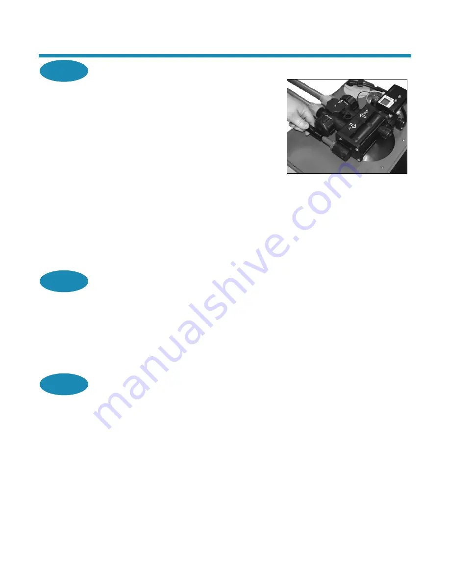
Connect Drain Line 

The drain line carries away the backwash water as part of the 
regeneration cycle. 

A.


Connect the drain line to the drain end cap  
(See Figure 5) with a minimum 5/8-inch I.D. tubing 
(supplied). The size cannot be reduced. 

1.


To prevent leakage, wrap the threads on the drain 
fitting three times with 1/2-inch wide Teflon tape, or 
use plumber’s putty. 

2.


Screw the drain fitting (See Figure 5) into the drain 
end cap until fewer than three threads are visible. 


Figure 5: Connect Drain Line 

B.


Route the drain line to a floor drain, laundry tub, or other suitable waste receptor. Maintain a minimum 
2-inch (5-cm) air gap between the drain line and the flood level rim of the waste receptor to prevent 
back-siphoning. This drain line should make the shortest run to the suitable drain. 

C.


The drain line may be elevated up to 8 feet (2.4 m) from the discharge on the appliance as long as 
the water pressure in your system is 40 psi (2.8 bar) or more. 

D.


If the drain line is 25 feet (7.6 m) or longer, increase the drain line and adapter to 3/4-inch I.D. The 
end of the drain line must be equal to or lower in height than the control valve. 

Caution: The drain line must not be kinked, crimped, or restricted in any way. 

Step 6


Flush Lines 

A.


Place the appliance in the Bypass position. (See Figure 6.) 

B.


Turn on the main water supply. 

C.


Open the nearest cold water faucet to flush the plumbing of any excess soldering flux, air, or any 
other foreign material. 

D.


Return the appliance to Normal Operation. 

Note: 

To prevent untreated water from entering your home, remember to not use water inside your 

home when the appliance is in Bypass mode. Remember to return the appliance to Normal Operation 
when you have finished using untreated water. 

Step 7


Check for Leaks 

A.


Close all faucets. 

B.


Check all lines and connections for leaks. If leaks are found: 

1.


Turn off the main water supply. 

2.


Open a cold water faucet to depressurize the lines. 

3.


Close the faucet to eliminate any siphoning action. 

4.


Repair all leaks. 

5.


Turn on the water supply. 

6.


Place the appliance in the Service position to slowly fill the media tank. (See Figure 6.) 

7.


Open a cold water faucet to purge air out of the media tank. 

8.


Close the faucet and recheck for leaks. 

WaterBoss Softener Two-Button Owner’s Manual 

5/12/2011 

Summary of Contents for PRO180

Page 1: ...P PR RO O1 18 80 0 A AN ND D P PR RO OP PL LU US S3 38 80 0 O OW WN NE ER R S S M MA AN NU UA AL L A AN ND D I IN NS ST TA AL LL LA AT TI IO ON N G GU UI ID DE E V VE ER RS SI IO ON N 1 1 0 0 T TW WO O B BU UT TT TO ON N ...

Page 2: ...ling these substances in the system specifications other special treatment of the water supply must be used to remove these substances before they enter this product Otherwise WaterBoss shall have no obligations under this warranty This warranty does not cover damage to a part or parts of the system from causes such as fire accidents freezing or unreasonable use abuse or neglect by the owner This ...

Page 3: ...4 836 9876 Help is also available on the WaterBoss website www waterbosspro com The HelpLine is available to answer questions about specific water problems appliance installation and operation When calling the HelpLine please have this guide and the serial number of your appliance available WaterBoss 4343 S Hamilton Rd Groveport OH 43125 Warning This appliance must be applied to potable water only...

Page 4: ...appliance runs out of salt A Open the salt lid and add salt B Wait two hours then press and hold the R button for 5 seconds C Regeneration is complete after approximately 12 to 45 minutes and the appliance is returned to Normal Operation 8 If dirt sand or large particles are present in the water supply the appropriate WaterBoss filter can eliminate this problem 9 The appliance may be disinfected w...

Page 5: ... for every 1 ppm 1 mg L of ferrous iron Water Characteristics Softeners require a pH of 7 or above to function properly An iron test to determine iron levels is also necessary The 900 NF Acid Neutralizing Filter adjusts pH levels of 6 3 or above Water Hardness Double check hardness of water with test strips provided to verify that your appliance is right for the job Model Pro180 will condition wat...

Page 6: ... outlet of the appliance to the inlet of the water heater Do Not 1 Do not install if checklist items are not satisfactory See Checklist Before Installation 2 Do not install if the incoming or outlet piping water temperature exceeds 120 F 49 C See Specifications 3 Do not allow soldering torch heat to be transferred to valve components or plastic parts when using the optional copper adapters 4 Do no...

Page 7: ...placement area is clean B Turn off the electricity and water supply to the water heater For gas water heaters turn the gas cock to Pilot C Examine the inlet plumbing to ensure that the pipe is not plugged with lime iron or any other substance Clean or replace plugged plumbing Note A pipe with a minimum of 3 4 inch I D is required between the pressure tank and the appliance for the appliance to fun...

Page 8: ...for 3 4 inch copper plumbing or 3 4 inch CTS CPVC plastic tubing Ensure that the three components 1 collar 2 metal retaining ring and 3 nylon sleeve are correctly installed in sequence on the pipe See Figure 2 Note Teflon tape or plumber s putty is NOT necessary and should NOT be used with Qest fittings Figure 2 Qest Fittings D Attach the water lines to the appliance in compliance with all state a...

Page 9: ...e drain line and adapter to 3 4 inch I D The end of the drain line must be equal to or lower in height than the control valve Caution The drain line must not be kinked crimped or restricted in any way Step 6 Flush Lines A Place the appliance in the Bypass position See Figure 6 B Turn on the main water supply C Open the nearest cold water faucet to flush the plumbing of any excess soldering flux ai...

Page 10: ... Step 11 Fill the Brine Cabinet With Salt A Fill the brine cabinet with salt Use clean white pellet or solar salt Do not mix pellet with solar salt Note Always keep the salt level above the water level For convenience completely fill the tank when refilling with salt B After you add salt including adding it after the tank has run out of salt wait two hours for saturated brine before starting any r...

Page 11: ...ter To prevent untreated water from entering the home water should not be used inside the home when the appliance is in Bypass mode Ensure that the appliance is returned to Normal Operation when the appliance is repaired or the use of untreated water is complete by turning the knob to Service To blend hardness back into the water using the bypass turn the knob slightly from the Service position to...

Page 12: ...of soft water remaining until the next automatic regeneration Typically each person in the household uses about 75 gallons 284 L per day Water remaining is in gallons or liters in hundreds For example 5 500 gallons 19 1900 liters Recharge Regeneration Status Shows regeneration cycle numbers during regeneration The display will blink the cycle number The blinking regeneration numbers are First cycl...

Page 13: ...minate iron buildup in the resin bed Salt with an iron cleaning agent or iron out cleaner is recommended for continuous use as a preventive measure against iron fouling of the resin bed Properly using this feature and following these tips will help to ensure a long service life for your appliance Button Function P Used to program and save Customer Settings R Used to change Customer Setting values ...

Page 14: ...General Information on page 3 of this manual C Use the following example to determine the controller setting Your Water English Example Metric Example Enter hardness grains per gallon mg L x 10 20 34 If your water contains 3 ppm mg L iron add 15 26 15 26 The sum is your controller setting number 32 60 Increase your water hardness setting by 5 grains per gallon 8 6 mg L x 10 for every 1 ppm mg L of...

Page 15: ...s per pound 570 grams kg of salt This choice meets or exceeds the requirements some states currently have in regards to salt efficiency 2 S2 will provide more capacity between regenerations than S1 3 SA is the automatic salt setting that uses the average daily water usage to determine an appropriate salt dosage not to exceed the appliance s maximum capacity Note This salt setting is recommended fo...

Page 16: ... setting is displayed press the P button Step 5 Set 96 Hour Mode A The 96H indicator will blink and the display reads indicating the default status of on B Press the R button to cycle between and If the 96 Hour mode is on the 96H indicator is displayed during Normal Operation The 96 Hour mode prevents the appliance from going longer than 4 days without a regeneration Note If there is iron in your ...

Page 17: ...The indicator bar below the digits will blink and the display reads designating the default of English units gallons B Press the R button to cycle between off and on Choosing will set the units to metric liters When metric units are active the indicator bar below the digits is displayed during Normal Operation C When the desired setting is displayed press the P button Step 3 Restore Factory Defaul...

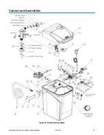
Page 18: ...Cabinet and Assemblies Figure 10 Cabinet and Assemblies WaterBoss Softener Two Button Owner s Manual 5 12 2011 18 ...

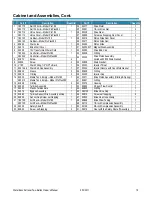
Page 19: ...itting 1 2 NPT x Barb 1 36 93223 Injector Throat 1 11 90614 3 0 Drain End Cap Assembly 1 37 53224 Injector Nozzle with Over Mold Gasket 1 12 93835 Sleeve 2 38 93806 O Ring 1 13 90819 O Ring 2 39 53235 Injector Cap 1 14 93530 Media Tank Empty Model Pro180 1 40 53511 Brine Piston Assembly O Ring Spring 1 380210 Media Tank Empty Model ProPlus380 41 90821 O Ring 1 15 93838 O Ring 2 42 53510 Housing 1 ...

Page 20: ...ective transformer Test with volt meter for 12 VAC at control If less than 10 VAC or greater than 14 VAC replace the transformer No read out in display Defective circuit board With 12 VAC present at controller replace the controller Controller not attached properly Make sure the controller is pushed all the way onto the drive end cap Defective magnet disk Replace magnet disk Appliance stays in reg...

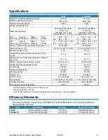
Page 21: ...0 3 L min psi bar 15 1 0 14 6 1 0 Maximum flow rate to drain during regeneration backwash gpm L min 3 0 11 4 3 0 11 4 Minimum Maximum Water Pressure psi bar 20 120 1 4 8 3 20 120 1 4 8 3 Minimum water flow required gpm L min 3 0 11 4 3 0 11 4 Controller type 2 Button 2 Button Frequency of regeneration Demand Demand Salt storage lb kg 120 55 170 78 Height in cm 25 5 64 8 33 4 84 8 Footprint in cm 1...

Page 22: ...Notes ...

Page 23: ...Notes ...

Page 24: ...WaterBoss has these third party listings In Business Since 1956 www waterbosspro com 4343 South Hamilton Road Groveport OH 43125 LITHO USA 2011 180380 RV0511HQWI ...

Reviews: