3
38
38. Drain valve
Service
Manual
Description
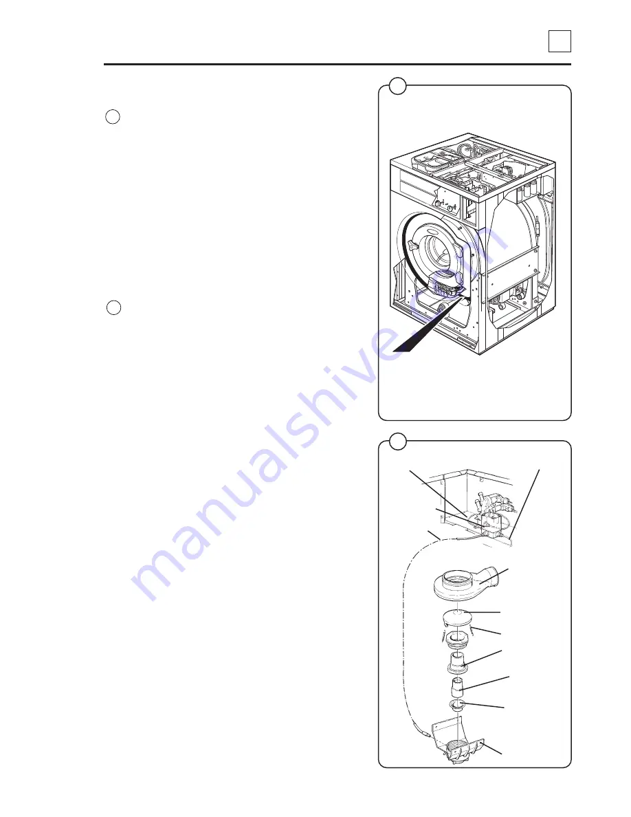
The drain valve is situated on a flange at the
bottom of the outer drum and can be accessed
from the front after removing the front cover.
The drain valve consists of the following principal
parts:
•
Lower part with rubber diaphragm.
•
Piston and cylinder.
•
Pressure plate and recoil springs.
•
Rubber diaphragm with drain connection.
•
Upper part with connection for outer drum.
Function
The drain valve uses the water pressure in the
cold-water inlet to close the valve. A feed hose is
connected between the water inlet and the
control valve.
When the control valve operates (drain valve
should be closed), the control valve opens the
water pressure onto the feed hose, which is
connected to the lower part of the drain valve.
When the lower part is filled with water, the lower
part diaphragm pushes up the piston. The piston
lifts the pressure plate against the drain valve
rubber diaphragm, which in turn forms a seal
against the outer drum, effectively closing the
valve.
When the drain valve should be opened, the
control valve changes position to allow the water
pressure to the lower part of the drain valve to
close, instead opening the return hose to the
drain. The pressure plate recoil springs pull the
pressure plate back, upon which the piston is
pressed back into the cylinder. The water from
the lower part is fed through the feed hose and
the control valve to the drain.
3359
Cylinder
Feed hose
Control valve
Feed hose
Lower part
Diaphragm
Piston
Pressure plate
Rubber
diaphragm
with drain
connection
Return hose
Recoil springs
Drain valve
5916
Principal
diagram
Fig.
1
Fig.
2
1
2
Summary of Contents for W620 Classic
Page 1: ...DOC NO 438 9205 85 07 EDITION 49 2004 W620 W630 W640 W655 W675 Classic SERVICE MANUAL ...
Page 2: ......
Page 4: ...Intentionally blank ...
Page 6: ...Intentionally blank ...
Page 10: ...Intentionally blank ...
Page 12: ...Intentionally blank ...
Page 13: ...1 1 1 Safety precautions Service Manual Contents Safety precautions 3 ...
Page 14: ...Intentionally blank ...
Page 16: ...Intentionally blank ...
Page 17: ...2 Technical data Contents Technical data 3 Connections 3 ...
Page 18: ...Intentionally blank ...
Page 28: ...Intentionally blank ...
Page 30: ...Intentionally blank ...
Page 37: ...11 Regular maintenance Contents Daily 3 Every third month 3 ...
Page 38: ...Intentionally blank ...
Page 42: ...Intentionally blank ...
Page 58: ...Intentionally blank ...
Page 61: ...27 Thermostat Contents Data 3 Description 3 Repair instructions 4 Replacing the thermostat 4 ...
Page 62: ...Intentionally blank ...
Page 66: ...Intentionally blank ...
Page 76: ...Intentionally blank ...
Page 78: ...Intentionally blank ...
Page 79: ...3 30 30 Motor Service Manual Warnings DANGER Be careful when measuring capacitors and filter ...
Page 85: ...38 Drain valve Contents Description 3 Function 3 Repairs 4 Disassembly 4 Assembling 5 ...
Page 86: ...Intentionally blank ...
Page 90: ...Intentionally blank ...
Page 91: ...39 Detergent compartment Contents Description 3 ...
Page 92: ...Intentionally blank ...
Page 94: ...Intentionally blank ...
Page 96: ...Intentionally blank ...
Page 100: ...Intentionally blank ...
Page 102: ...Intentionally blank ...
Page 108: ...Intentionally blank ...
Page 114: ...Intentionally blank ...
Page 132: ......

