


8
INST
INST
INST
INST
INSTALLA
ALLA
ALLA
ALLA
ALLATION
TION
TION
TION
TION
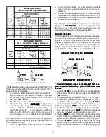
1. GAS CONNECTION
(Gas dryers only)
a. Remove the shipping cap from gas pipe at the rear of
the dryer.
NOTE:
NOTE:
NOTE:
NOTE:
NOTE: DO NOT
DO NOT
DO NOT
DO NOT
DO NOT connect the dryer to L.P. gas service without
converting the gas valve. An L.P. conversion kit (P/N
131776600) must be installed by a qualified gas
technician.
b. Connect a 1/2 inch (1.27 cm) I.D. semi-rigid or approved
pipe from gas supply line to the 3/8 inch (0.96 cm) pipe
located on the back of the dryer. Use a 1/2 inch to 3/8
inch (1.27 cm to 0.96 cm) reducer for a connection.
Apply an approved thread sealer that is resistant to the
corrosive action of liquefied gases on all pipe connections.
c. Open the shutoff valve in the gas supply line.
d. Test all connections by brushing on a soapy water solution.
NEVER TEST FOR GAS LEAKS WITH AN OPEN FLAME.
NEVER TEST FOR GAS LEAKS WITH AN OPEN FLAME.
NEVER TEST FOR GAS LEAKS WITH AN OPEN FLAME.
NEVER TEST FOR GAS LEAKS WITH AN OPEN FLAME.
NEVER TEST FOR GAS LEAKS WITH AN OPEN FLAME.
2. Connect the exhaust duct to outside exhaust system. Use
duct tape to seal all joints.
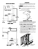
3. With the dryer in its final position, adjust one or more of the
legs until the dryer is resting solid on all four legs. Place a
level on top of the dryer. THE DR
THE DR
THE DR
THE DR
THE DRYER MUST BE LEVEL
YER MUST BE LEVEL
YER MUST BE LEVEL
YER MUST BE LEVEL
YER MUST BE LEVEL
AND RESTING SOLID ON ALL FOUR LEGS.
AND RESTING SOLID ON ALL FOUR LEGS.
AND RESTING SOLID ON ALL FOUR LEGS.
AND RESTING SOLID ON ALL FOUR LEGS.
AND RESTING SOLID ON ALL FOUR LEGS. Turn the lock
nuts on each of the four legs up toward the base of the
dryer and snug with a 1/2 inch open end wrench.
4. Plug the power cord into a grounded outlet. NOTE: Check
to ensure the power is off at circuit breaker/fuse box before
plugging the power cord into the outlet.
5. Turn on the power at the circuit breaker/fuse box.
Before operating the dryer, make sure the dryer
area is clear and free from combustible materials, gasoline,
and other flammable vapors. Also see that nothing (such as
boxes, clothing, etc.) obstructs the flow of combustion and
ventilation air.
6. Run the dryer through a cycle check for proper operation.
NOTE:
NOTE:
NOTE:
NOTE:
NOTE: On gas dryers, before the burner will light, it is
necessary for the gas line to be bled of air. If the burner
does not light within 45 seconds the first time the dryer is
turned on, the safety switch will shut the burner off. If this
happens, turn the timer to "OFF" and wait 5 minutes before
making another attempt to light.
7. Place these instructions in a location near the dryer for future
reference.
NOTE:
NOTE:
NOTE:
NOTE:
NOTE: A wiring diagram is located inside the dryer.
REPLACEMENT P
REPLACEMENT P
REPLACEMENT P
REPLACEMENT P
REPLACEMENT PAR
AR
AR
AR
ARTS
TS
TS
TS
TS
If replacement parts are needed for your dryer, contact the
source where you purchased your dryer, or call (516)371-0700
for the Wascomat Authorized Parts Distributor nearest you.
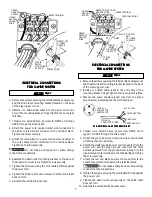
Label all wires prior to disconnection when
servicing controls. Wiring errors can cause improper and
dangerous operation. Verify proper operation after servicing.
Destroy the carton and plastic bags after the
dryer is unpacked. Children might use them for play. Cartons
covered with rugs, bedspreads, or plastic sheets can become
airtight chambers causing suffocation. Place all materials in a
garbage container or make materials inaccessible to children.
The instructions in this manual and all other
literature included with this dryer are not meant to cover every
possible condition and situation that may occur. Good safe
practice and caution MUST
MUST
MUST
MUST
MUST be applied when installing, operating
and maintaining any appliance.
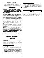
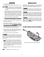
Lint Blade Retaining Pin Location and Orientation
Lint Blade Retaining Pin Location and Orientation
Lint Blade Retaining Pin Location and Orientation
Lint Blade Retaining Pin Location and Orientation
Lint Blade Retaining Pin Location and Orientation
Install the pins after the lint blade is installed.


