


Wärtsilä JOVYSTAR
– DELTA 40 – 150kVA BAX 4647E - 35 -
Fault signal
Description
Fault correction
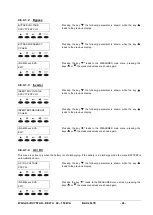
A10
BATTERY FAULT
Test of the battery has failed (see A11 Battery test).
In case of this alarm check the battery (connection, status of
the cells, voltage and so on). After you have solved the
problem you must go in the special menu and reset the UPS
to clear the alarm.
A11
BATTERY IN TEST
Battery test is in progress. The test is performed by
reducing the rectifier DC voltage and discharging the
battery. The battery voltage is being measured during this
test. Possible results are: Battery OK or Battery fault
Look-out for the test result.
A12
PLL FAULT
Internal Phase-Locked-Loop has failed.
Call the JOVYATLAS-service department.
A13
INVERTER OUT TOL
Inverter output voltage is out of tolerances. This is also
true during inverter off.
If the inverter is off check for the other alarms as A4 thermal
image, A23 EPO bus to understand why the inverter has
been switched off.
A14
OVERLOAD
UPS load > 100% of nominal power. The output amme-
ters measure the output current. The alarm becomes
active in case of exceeding current and the thermal image
protection (see A4 thermal image) starts to calculate the
thermal pulse.
Remove overload.
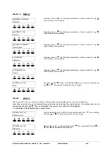
A15
BYPASS FAULT
Emergency line is not available as bypass. The emergen-
cy line is checked by frequency, RMS value and instan-
taneous value.
Check if the emergency line is ok; check if the SBCB is
closed and for the units which have protection fuses on the
emergency line check that fuses. If the above points are
correct and the alarm is still present, call the JOVYATLAS-
service department.
A16
BYPASS FEED LOAD
Emergency line (bypass) is feeding the load. This is also
true in case the inverter is off (check for the alarm A13
Inverter out of tolerance).
If the inverter is off check for the other alarms as A4 thermal
image, A23 EPO bus to understand why the inverter has
been switched off. This alarm can also come if there is the
retransfer blocked condition (see A17 Retransfer blocked) or
the bypass switch has been moved in bypass position (see
A22 Bypass switch). The load can be temporary transferred
to the bypass also in case of a short circuit (see A25 Short
circuit).
A17
RETRANSFER BLOCK
Load cannot be transferred back to inverter. This could
happen due to heavy load steps (like starting motors,
printers and so on) in a very short time. In this case as the
current exceeds two times the nominal value, the short
circuit monitor (see A25 Short circuit) transfers automati-
cally the load to bypass and after few seconds returns
back to inverter operation. If this happens three times in
one minute, the UPS blocks transferring the load.
You can reset this condition by sending the command
RESET or by making the reset of the UPS from the special
menu.
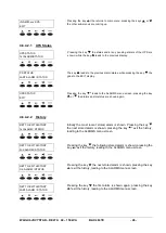
A18
MANUAL BYP CLOSE
Manual bypass circuit breaker MBCB is closed. This
signal comes from the MBCB circuit breaker auxiliary
contact.
Check if the MBCB auxiliary contact is ok. If the auxiliary
contact signal comes correctly to the I/S CL and the problem
is still present, call the JOVYATLAS-service department.
A19
OCB OPEN
Output circuit breaker OCB is open. This signal comes
from the OCB circuit breaker auxiliary contact.
Check if the OCB auxiliary contact is ok. If the auxiliary
contact signal comes correctly to the I/S-CL and the problem
is still present, call the JOVYATLAS-service department.
A20
OPTION
It is possible to program this message customer suited.
A21
HIGH TEMPERATURE
Thermal switch on the bridge heat sink has stopped the
inverter. This protection works as follows: the thermal
switch on the inverter bridge heat sink is normally closed.
As the temperature exceeds 80°C the thermal switch
opens, which in turn stops the inverter.
Check the temperature of the heat sink and check if the fans
are correctly working. Check also environmental temperature
and the load conditions. Check the alarm history and search
for alarms like A14 Overload, A4 Thermal image.
Check the thermal contacts if they are closed. If not check
which thermal switch is open and substitute it; otherwise
contact the JOVYATLAS-service department.
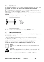
A22
BYPASS SWITCH
The UPS is equipped with a bypass-service-switch which
forces the load to bypass. If this switch is in the Bypass
position the alarm A22 is active and the load is trans-
ferred to bypass.
Check if the bypass switch is in Normal position. If not move
the switch in this position.
If the switch is in Normal position but the alarm is still pre-
sent, check the switch. If it is ok, call the JOVYATLAS-
service department.
A23
EPO BUS
The UPS is equipped with an emergency push-button or
terminals which stops the systems electronically (both the
inverter and the bypass off). If this button is pressed the
alarm A23 becomes active.
CAUTION:
This push button doesn’t insulate the UPS
from the mains. Disconnect the UPS as
indicated in the Manual Bypass procedure
before start maintenance.
Check if the button is pressed. If yes press it again and the
UPS will restart.
If the button is not pressed but the alarm is still present,
check the push-button. If it is ok, call the JOVYATLAS-
service department.
A24
CURRENT STOP
Current through the inverter bridge has exceeded the
maximum limit. The hall effect ammeter TA1 transmits
the inverter bridge current to the inverter control logic.
Check if there is some IGBT or IGBT’s driver broken; check
also all the power supplies on the control PCB’s. If all seems
to be ok restart the unit and check the modulation on the
IGBT’s. Otherwise substitute the broken components before
to restart the unit as above explained.
If the alarm condition happens again, call the JOVYATLAS-
service department.
A25
SHORT CIRCUIT
Short circuit at the output of the inverter. If possible the
load is automatically transferred to bypass.
Check if the load is too high or there are heavy load steps
(like starting motors, printers and so on).
Check the alarm A24 Current stop is present. If so see the
above point. Check also the inverter bridge (drivers and
IGBT’s), the PS HV power supply and the hall effect amme-
ter.
If the above points are correct, call the JOVYATLAS-service
department.