


WINCH MANUAL
HYDRAULIC PRINCIPAL CHART AND INSTALLATION:
6
–
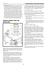
Plumbing Connections
: Keep all hoses away from any areas where
heat may be considered too extreme such as an exhaust, turbo or
any moving parts. Lines should not be allowed to rub on any rotating,
abrasive, or vibrating surfaces. In some applications, 90°fittings on
the directional valve and motor or balance valve are necessary to
make hose mounting more flexible. After plumbing has been laid out
on vehicle, install O-ring seals to valves and connections.. Torque
tight. Do not over tighten any fittings. Install O-ring seals on Winch
Motor. Torque tight. Connect any hose port A on motor or port V1 on
balance valve to port A on directional valve, port B on motor or port V2
on balance valve to port B on directional valve, port P on directional
valve to pump’s high-pressure port, port T on valve to reservoir, if
necessary Connect any hose port on valve to steering box. Attach any
O-ring or seal from vehicles original tube fitting to tube fitting.
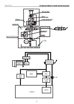
HYDRAULIC PRINCIPAL CHART AND
INSTALLATION:
Warning
A
A
A
A
B
B
B
B
P
P
P
Oil out
Selector
Valve
Oil in
P
T A
B
P
T
T
T
T
“H” Type “Y” Type
“M” Type
“O” Type
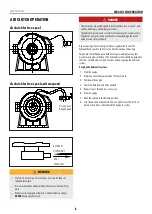
Hydraulic control valves are an essential component for optimizing system
performance. They’re used to regulate the flow rate and pressure of the
hydraulic oil as it passes through a hoses or pipes, always maintaining the
speed and pressure.
Hydraulic flow control valves are adept at controlling the flow of these
liquids from the pumps to cylinders and motors. Their primary function is
to regulate the flow and direction rate within a specific area of a hydraulic
circuit. At the same time, they also control the transfer rate of energy
across all pressure levels.
A selector valve is used to control the direction of movement of a
hydraulic actuating cylinder or similar device. It provides for the
simultaneous flow of hydraulic fluid both into and out of the unit. Hydraulic
system pressure can be routed with the selector valve to operate the
unit in either direction or a corresponding return path for the fluid to the
reservoir is provided. There are two main types of selector valves: open-
center and closed-center. An open center valve allows a continuous flow
of system hydraulic fluid through the valve even when the selector is not in
a position to actuate a unit. A closed-center selector valve blocks the flow
of fluid through the valve when it is in the NEUTRAL or OFF position.
Selector valve choice as follows:
(H type and Y type are available, O type and M type is not available)
There are three positions for the selector valve. This means the Solenoid
directional/selector valve spool has three working positions, both ends of
the valve are solenoid coil control action.
–
A’ coil is energized, and ‘B’ coil is powered off, the spool moves to the
direction of the ‘A’ coil.
–
B’ coil is energized, and ‘A’ coil is powered off, the spool moves in the
direction of the ‘B’ coil.
–
‘A’ and ‘B’ coils are powered off at the same time, the solenoid valve
spools back to the middle position, forming a closed loop, that is, the
two chambers of the cylinder are completely closed, resulting in no
movement.
The valve has four channels: P, T, A and B.
‘P’ is for oil In, ‘T’ is for oil Out, ‘A’ and ‘B’ is for output.
When the electromagnet is not energized, the reversing valve is in the
middle position. The PTAB is connected to each other in the middle of ‘H’
type. In the middle position of ‘Y’, TAB is connected to each other, and P
is disconnected from other routes. Type 0 directional valve in the PTAB
access is blocked. In the middle position of ‘M’ type, PT communicates
with each other, ‘A’ does not communicate with other, and ‘B’ does not
communicate with other.
“H” type: all oil ports are connected, the system is unloaded, and the
cylinder is floating. Hydraulic cylinder is connected to oil tank in two
chambers, from static stop to start impact. When braking, the oil port is
interconnecting, and the braking is more stable than the “O” type, but the
reversing position changes greatly.
“Y” type: the oil pump does not unload, the hydraulic cylinder is
connected to the oil tank in two chambers, there is impact from rest to
start, and the braking performance is between “O” type and “H” type.
“O” type: all oil ports are closed and the system does not unload.
Hydraulic cylinder filled with oil, smooth from rest to start. When braking
motion inertia caused by hydraulic impact. High accuracy of reversing
position.
“M” type: oil pump unloading, from rest to start smoothly. The braking
performance is the same as the “O” type.


