Tension Control System
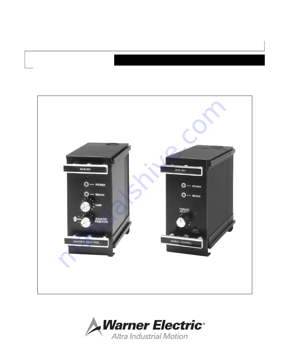
MCS-166, MCS-203, MCS-204
Installation & Operation Instructions
P-0257-WE819-9027
Page 1: ...Tension Control System MCS 166 MCS 203 MCS 204 Installation Operation Instructions P 0257 WE 819 9027...
Page 2: ...tem Troubleshooting MCS 166 MCS 203 21 22 MCS 166 MCS 204 23 Replacement Parts Listing 24 Listing of Figures and Illustrations 24 Notes Installation must be made in accordance with the instructions fo...
Page 3: ...motely by external potentiometer voltage input or current loop input The MCS 605 1 or TCS 605 5 Pivot Point Sensors provide the dancer position signal to the MCS 203 Dancer Control The MCS 605 1 is co...
Page 4: ...correspond to minimum output level Torque Adjust Span Provides for either manual adjust or span adjustment when in all other modes of operation General Information Control chassis must be considered...
Page 5: ...0 bolts c Apply the terminal strip label supplied with the control logic module to the PC Board as shown in Figure 2 page 6 CAUTION Be sure to apply the label in the proper position with the brake ter...
Page 6: ...r 4 13 64 mounting holes for each housing to provide clearance for the 10 mounting studs 4 Slide the housing assemblies into the mounting panel cutouts Securely fasten the housings to the mounting pan...
Page 7: ...shaft and pin are aligned and separated by 5 16 6 While holding the sensor and bracket in this position mark the centers of the bracket holes on the machine 7 Drill and tap three 3 holes for 8 32 scr...
Page 8: ...tation as viewed from the connector end of the pivot point sensor CW a For CW rotation connect sensor wires as follows Black to Terminal 5 green to Terminal 6 red to Terminal 7 Shield lead should be c...
Page 9: ...Warner Electric 800 825 9050 P 0257 WE 819 9027 9 Figure 7 MCS 166 MCS 203 Wiring Single Brake Figure 8 MCS 166 MCS 203 Wiring Dual Brakes...
Page 10: ...moving the roll follower pot toward the core will decrease voltage at terminal 6 c Voltage Source Input Connect side of external voltage source to terminal 6 and side or common of external voltage so...
Page 11: ...ont housings if either wall or shelf mounting is used Secure the latches If shelf mounting is used secure the housings with the four 4 bolts for each section 8 Do not insert the control modules at thi...
Page 12: ...12 Warner Electric 800 825 9050 P 0257 WE 819 9027 Figure 11 MCS 204 Input Configuration Figure 12 Analog Photoelectric Roll Follower Wiring...
Page 13: ...ide to side until the connectors mate but do not apply excessive force NEW STYLE UNITS WITH RIBBON CABLES Pull the ribbon cable forward so that the connector end is in front of the housing assembly Fa...
Page 14: ...rify that power is on 2 Start the machine and draw material 3 After the Dancer has stabilized adjust the front panel Dancer Position potentiometer for the desired dancer running position 4 If the syst...
Page 15: ...r response is not achieved with R16 at maximum CW setting the next higher differentiator response range should be used CAUTION When switching to higher response ranges R16 should be set full CCW Facto...
Page 16: ...16 Warner Electric 800 825 9050 P 0257 WE 819 9027 Figure 13 Control Adjustment Locations MCS 166 MCS 203...
Page 17: ...to side until the connectors mate but do not apply excessive force NEW STYLE UNITS WITH RIBBON CABLES Pull the ribbon cable forward so that the connector end is in front of the housing assembly Faste...
Page 18: ...eter through front panel so the 0 100 indicator illuminates This is a true zero output to the brake c Now rotate the torque span potentiometer toward its maximum setting As the pot is turned the 0 100...
Page 19: ...h corresponds to the exact center of the roll shaft Adjust the roll follower potentiometer to provide a DC input reading of 0 5 VDC 0 1 VDC d Remove the meter from the follower potentiometer and conne...
Page 20: ...20 Warner Electric 800 825 9050 P 0257 WE 819 9027 Figure 14 Control Adjustment Locations MCS 166 MCS 204...
Page 21: ...ck to be sure lead wires to the brake are at the brake terminals 1 and 2 of the control Check to see if sensor is connected Using a voltmeter check for approximately 1 8 to 28 VDC between the brake te...
Page 22: ...does not exceed the minimum allowable torques if the voltage did reduce to zero but did not reverse polarity adjustment of the antiresidual may be necessary If adjustment of the antiresidual does not...
Page 23: ...does not have the torque capacity required for the application Verify that the correct brake was selected by repeating the selection procedure Brake is not releasing as input level decreases Check th...
Page 24: ...23 Rear P C Board Assy MCS 204 W S end 6910 101 021 Fuse 3 Amp 250 Volt Fast Acting 458 8001 006 MCS 605 1 Pivot Point Sensor Single Turn 7330 448 002 TCS 605 5 Pivot Point Sensor 5 Turn 7330 448 003...