Warn 87190 Installation Instructions Manual Download Page 8

©2011 Warn Industries, Inc.WARN® and the WARN logo are trademarks of Warn Industries Inc.

 8 

87197 A1


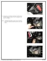
11.  Install mount tabs onto inside of push tube assembly 

flanges.  Pucks need to be facing inward and away from 

plow blade.  Fasteners are included in the push tube kit.

12. Reconnect battery ground.


Operation:

1.    Stage the plow assembly on level solid ground.  See Plow 

operator guide “Installing the Plow” for more information.

2.    SLOWLY drive the vehicle up to the plow assembly with the 

vehicle as square to the plow as possible.

3.    Turn off the vehicle and set the parking brake.  Lift the plow 

mount flange end of the push tube assembly up to the plow 

mount on the vehicle.  Insert the plow mount flange into the 

plow mount. 

4.    Double check that the plow is fully engaged with the plow 

mount, resting on the two lower ¼” socket bolt heads. 

5.    With both alignment pucks seated into the plow mount the 

retaining pins can be inserted. Once inserted the retaining 

clips on the pins can be clipped through the hole in the 

back of the plow mount bracket. See Plow operator guide 

“Installing the Plow” for more Information.  The parts list 

view shown at the beginning of this document shows the 

pin location details for this application.

6.    Attach the winch line to the push tube assembly through 

the rope guide as described in the Plow operators guide, or 

attach the electric plow lift.

7.    Turn the ignition switch to ON, and operate the winch 

or electric lift to lift and lower the plow. The plow is now 

ready for operation. Read the Plow Operators Guide before 

operating plow.

Summary of Contents for 87190

Page 1: ...the plow Always stay clear of moving parts and joints Always keep others away when operating or adjusting plow Always perform regular inspections and maintenance on the plow mechanism fasteners cable and related hardware Always replace all worn or damaged parts before operating Never operate this WARN product with damaged or missing parts Always drive slowly over bumpy and rough terrain Driving at...

Page 2: ...productifyouareunder16yearsofage Neveroperatethisproductwhenundertheinfluenceofdrugs alcoholormedications Read installation and operating instructions thoroughly N O T E S B E F O R E Y O U B E G I N T A B L E O F C O N T E N T S Tools Required page 2 Torque Specifications page 2 Parts List page 3 Installation page 4 8 Tips Troubleshooting page 9 Maintenance Care page 9 Before beginning plow mount...

Page 3: ...ET HEAD BOLT 5 6 10 MM CARRIAGE BOLT 6 2 8 MM U BOLT 7 1 LEFT MOUNT TAB 8 1 RIGHT MOUNT TAB 9 6 10MM NUT 10 2 8 MM BOLT 11 2 PIN 12 4 8 MM NUT 13 2 SPACER 14 4 8 MM WASHER 15 4 6 MM NUT NOT REQUIRED WHEN INSTALLED WITH WARN WINCH MOUNT A A NOTE WHEN CONNECTING PLOW TO MOUNT BRACKET THE PIN RETAINING WIRE INSTALLS THROUGH THE BACK OF THE PLOW MOUNT BRACKET PLOW PUSH TUBE ATTACHMENT HOLES ...

Page 4: ...N S T A L L A T I O N I N S T R U C T I O N S I N S T A L L A T I O N I N S T R U C T I O N S 1 Remove front 6mm bolts and clip pins from plastic guards 2 Partially remove bottom plastic guard and remove two lower factory front tube bolts 3 Remove A arm plastic guard c clip pin b 6mm bolt b b c b b c ...

Page 5: ...trademarks of Warn Industries Inc 5 87197 A1 4 Install plate over front differential and behind frame tubes Fasten using 8mm U bolt Do not tighten 5 Install bracket in front of frame tubes Fasten to plate using 10 mm carriage bolts and nuts Do not tighten ...

Page 6: ...Industries Inc 6 87197 A1 6 Install plow mount bracket under frame Fasten to frame and plate using 8mm bolts and 10mm carriage bolts and nuts Do not tighten Note If installing with the Warn winch mount remove and discard the u bolts that attach the winch mount to the frame ...

Page 7: ...tened to the frame using a spacer and washer 8 Tighten bolts to recommended torque specifications listed on page 4 and in the order shown 9 Install 6mm socket head bolts and nuts 10 Lift lower plastic guard up against the lower plow mount bracket and mark plastic for trimming Trim plastic as required for clearance Re attach lower plastic guards using bolts and clips removed in step 1 3 ...

Page 8: ...he plow mount flange into the plow mount 4 Double check that the plow is fully engaged with the plow mount resting on the two lower socket bolt heads 5 With both alignment pucks seated into the plow mount the retaining pins can be inserted Once inserted the retaining clips on the pins can be clipped through the hole in the back of the plow mount bracket See Plow operator guide Installing the Plow ...

Page 9: ...ow mount and related hardware prior to each use Replace all parts that appear rusted or deformed Inspect all nuts and bolts on the plow plow mount and related hardware prior to each use Tighten all nuts and bolts that appear to be loose Stripped fractured or bent bolts or nuts must be replaced Check all cables prior to use Replace cables that are worn or frayed Check all moving and rotating parts ...

Reviews: