background image

©2019 Warn Industries, Inc.WARN® and the WARN logo are trademarks of Warn Industries Inc. 

105724A0

I N S T A L L A T I O N   I N S T R U C T I O N S

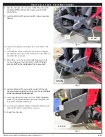
1.  Remove the bumper by removing the two torx head screws, 

two upper bolts and one lower  from each side of vehicle.  
Retain hardware.

2.  Slide bumper forward while carefully leveraging the plastic 

out of the way.

3.  Line up the new bumper mount (A3) with the stock bumper 

mounting location.

4.  Install one M8 bolts (B1) with washer (B2) through the top 

two mounting holes (each side).

5.  Insert one M8 bolt (B1) through bottom mounting hole 

(each side)

.  

NOTE:  This is to help hold mount up in place 

and will be removed in a later step.

6.  Secure upper bolts with one washer (B2) and lock nut 

(B3) 

(each side)

.  

NOTE: Tighten only the upper two bolts, 

washers and locknuts at this time.  

5.  Cut the plastic along the white line shown in the photo 

(each side)

.

6.  Install one factory torx head screw through plastic, upper 

mounting bracket and frame 

(each side)

.  

7.  Remove the lower mounting bolt 

(each side)

.

Torx head 

screws

Remove

Remove

Cut plastic

B1, B2 and 

B3

B1

Figure 2

Figure 3

Figure 4

Torx head 

screw

Lower mounting 

bolt

Summary of Contents for 104300

Page 1: ...IONS COULD LEAD TO SEVERE INJURY OR DEATH AlwaysKnowYourWinch TaketimetofullyreadtheInstructionsand orOperationsGuide and orBasicGuidetoWinchingTechniques inordertounderstandyourwinchanditsoperations Neverworkundervehiclebeforeproperlysecuringvehicle Alwaysuseappropriateandadequatecareinliftingcomponentsintoplace Neverworkundervehiclebeforeproperlysecuringvehicle Alwaysuseappropriateandadequatecar...

Page 2: ...gtechniqueorgetliftingassistancewhilehandlingandinstallingproduct Read installation and operating instructions thoroughly T O O L S R E Q U I R E D Standard and Metric wrenches Standard and Metric sockets Ratchet Extension Cutting tool T O R Q U E S P E C I F I C A T I O N S Please use the recommended torque specifications when assembling this product unless otherwise specified in the instructions...

Page 3: ...S L I S T Part Number Qty Description A1 1 BUMPER SHELL A2 1 FAIRLEAD PLATE A3 1 UPPER BUMPER MOUNT A4 1 SKID PLATE A5 1 LIGHT BRACKET B1 19 M8 X 25MM HEX HEAD BOLT B2 28 FLAT WASHER B3 11 M8 LOCK NUT B4 2 PLASTIC WASHER A1 A2 B1 B2 B3 A3 A4 B4 A5 I N S T A L L A T I O N I N S T R U C T I O N S Figure 1 ...

Page 4: ...r B2 through the top two mounting holes each side 5 Insert one M8 bolt B1 through bottom mounting hole each side NOTE This is to help hold mount up in place and will be removed in a later step 6 Secure upper bolts with one washer B2 and lock nut B3 each side NOTE Tighten only the upper two bolts washers and locknuts at this time 5 Cut the plastic along the white line shown in the photo each side 6...

Page 5: ...fer to exploded view on page 3 12 While lifting up on the skid plate slide the bumper shell A1 over the upper mounting bracket NOTE The skid plate should fit on the inside edge of the bumper shell 13 Install one M8 bolt B1 and one flat washer B2 through the lower bumper end cap mounting hole Do not continue all the way through the skid plate yet 14 Insert one plastic washer B4 over bolt NOTE The p...

Page 6: ...inch 22 Reach in through the side or the rear of the bumper and thread the four LONGER M8 bolts supplied in this kit up through bumper mount fairlead plate and into winch feet WARNING Do not use the M8 bolts supplied in your winch kit they will not be long enough 23 Torque all hardware per recommendations on page 3 B1 B2 B3 Figure 8 Figure 9 Figure 10 M A I N T E N A N C E C A R E 1 Inspect all pa...

Reviews: