4.5
Air Vents
On the system boiler an automatic air vent complete with its own check valve is fitted
to the top of the boiler heat exchanger. It is recommended that an air vent is fitted at
the highest point in the system. However where the pipework comes off the boiler and
drops down an automatic airvent should be fitted to the top of the boiler.
4.6
Drain Cock
Drain cock(s) should be fitted to the lowest points in the system to enable the system
to be fully drained. On the system boiler a drain cock has been fitted to the system
boiler heat exchanger.
4.7
Expansion Vessels
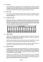
Refer to BS 7074: part 1 or BS 5449 for details of the pressure vessel sizing. The
values given in the table are for a total system values which includes the primary water
capacity. On the system boiler a 12 litre expansion vessel charged to 0.5 bar is supplied.
This can accommodate a maximum system volume of approximately 150 litres. If this
volume is exceeded an additional vessel will be required.
0.5
2.1
4.2
6.3
8.3
10.5
12.5
14.6
16.7
18.7
20.8
22.9
25.0
1.0
2.7
5.4
8.2
10.9
13.6
16.3
19.1
21.8
24.5
27.2
30.0
32.7
1.5
3.9
7.8
11.7
15.6
19.5
23.4
27.3
31.2
35.1
39.0
42.9
46.8
25
50
75
100
125
150
175
200
225
250
275
300
INITIAL
CHARGE
TOTAL
SYSTEM
VOLUME
VESSEL VOLUMES
4.8
System Filling
Water loss from a sealed system, as indicated by a reduction in pressure on the pressure
gauge, may be made up through a filling loop, however the cause of the water loss
should be fully investigated and corrected.
After filling, vent all air from the system. Ensure the caps on the automatic air vents are
loose, bleed the circulating pump and disconnect the temporary filling loop.
As standard, a filling point complete with a filling loop has been included within the
system boiler. A system pressure, when cold, of 1 bar is recommended.
4.9
System Pressure
The pressure relief discharge shall be positioned away from any electrical components.
No other valves should be positioned between the relief valve and the discharge, and
the discharge pipes should not be used for any other purposes. The discharge pipe
must be plumbed to an external drain in a position where the discharge can be seen
but cannot cause any injury or damage.
Where there is a catastrophic loss of water from the system the boiler thermostats
may fail to operate which would result in serious damage to the appliance. To prevent
this it is recommended that a low pressure cut out switch set at 0.2 bar is fitted to the
system and wired in series with the boiler thermostats.
Page 13


