
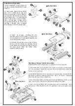

3) Insert - do not glue - Turntable Pin* (10)
through Frame and clip to Deck (11). Glue Front
(12) and Rear (13) Counterweight together and
to mounting points on Deck.
4) Carefully remove sprue from center of Track
(2x 14) and turn inside out. Carefully thread
center guides over Sprocket and Idler, resting on
the upper carrier rollers and bottom rollers
molded on Drive Frames
Do Not Glue
13
12
11
14
14
10
Do Not Glue
20
21
22
19
18
17
16
15
27
24
25
23
26
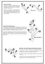
Machinery House Interior Assembly
PLEASE NOTE: All Winding Drums are designed to be moving parts.
1) Note raised area on front of Floor (15); insert - do not glue - Cable Drums*
(17) into openings in Right (16) and Left (18) Cable Sideframes; glue Side-
frames to Floor as shown.
2) Glue Boom Sideframe (19) to inset area on Floor as shown. Glue parts #20,
#21 & #22 as shown to build the Boom Drum; insert - do not glue - completed
Drum into openings in Boom Sideframe.
3) Glue Pinion Gear (23) to mounting point on Boom Sideframe. Insert - do not
glue - Gear Pin (24) through Gear and Drum Sideframe as shown.
4) Glue Left (25) and Right (26) Transmission Covers to Sideframes. Insert
open areas on Mounting Frame (27) into openings on Frame and glue in place.
1
2
3
6
9
8
7
7
8
9
4
6
5
Underframe Assembly
1) Glue Turntable (1) to Upper Frame (2)
and glue completed assembly to Lower
Frame (3).
2) Track Frames - Make 2: Insert - do not
glue - pins on Idlers* (2x 6; one each
side) into openings on rear of Right (4)
and Left (5) Track Frames. Glue Drive
Wheel Mounts (2x 7: one each left and
right) to raised area on front of Frame.
Push - do not glue - Shafts* (2x 9)
through Drive Wheels* (2x 8) and into
openings in Mounts. Glue completed
Drive Frames to left and right as shown.
Do Not Glue