background image

TABLE OF CONTENTS

Page

I - Introduction. . . . . . . . . . . . . . . . . . . . . . . . . . . . . . . . . . . . . . . . . . . . . . . . . . . . . . . . . . . . . . . . . . . . . . . . . . . . . . . 3
II - Safety instructions . . . . . . . . . . . . . . . . . . . . . . . . . . . . . . . . . . . . . . . . . . . . . . . . . . . . . . . . . . . . . . . . . . . . . . . . . 4,5
III - Equipment controls  . . . . . . . . . . . . . . . . . . . . . . . . . . . . . . . . . . . . . . . . . . . . . . . . . . . . . . . . . . . . . . . . . . . . . . . 6
 

A) Control panel pictograms  . . . . . . . . . . . . . . . . . . . . . . . . . . . . . . . . . . . . . . . . . . . . . . . . . . . . . . . . . . . . . . 6


B) Front and back view of the machine . . . . . . . . . . . . . . . . . . . . . . . . . . . . . . . . . . . . . . . . . . . . . . . . . . . . . . 7


C) Wand control buttons. . . . . . . . . . . . . . . . . . . . . . . . . . . . . . . . . . . . . . . . . . . . . . . . . . . . . . . . . . . . . . . . . . 8


D) Fume elimination system  . . . . . . . . . . . . . . . . . . . . . . . . . . . . . . . . . . . . . . . . . . . . . . . . . . . . . . . . . . . . . . 8

IV - Control panel  . . . . . . . . . . . . . . . . . . . . . . . . . . . . . . . . . . . . . . . . . . . . . . . . . . . . . . . . . . . . . . . . . . . . . . . . . . . . 9
 

A) Main power switch  . . . . . . . . . . . . . . . . . . . . . . . . . . . . . . . . . . . . . . . . . . . . . . . . . . . . . . . . . . . . . . . . . . . 9


B) Wand selector switch. . . . . . . . . . . . . . . . . . . . . . . . . . . . . . . . . . . . . . . . . . . . . . . . . . . . . . . . . . . . . . . . . . 9


C) Voltage regulating switch  . . . . . . . . . . . . . . . . . . . . . . . . . . . . . . . . . . . . . . . . . . . . . . . . . . . . . . . . . . . . . . 9


D) Solution pump switch  . . . . . . . . . . . . . . . . . . . . . . . . . . . . . . . . . . . . . . . . . . . . . . . . . . . . . . . . . . . . . . . . . 10


E) Indicator lights. . . . . . . . . . . . . . . . . . . . . . . . . . . . . . . . . . . . . . . . . . . . . . . . . . . . . . . . . . . . . . . . . . . . . . . 10


F) Accessory outlet. . . . . . . . . . . . . . . . . . . . . . . . . . . . . . . . . . . . . . . . . . . . . . . . . . . . . . . . . . . . . . . . . . . . . . 10

V - Start-up procedure . . . . . . . . . . . . . . . . . . . . . . . . . . . . . . . . . . . . . . . . . . . . . . . . . . . . . . . . . . . . . . . . . . . . . . . . . 11
 

A) What is included in the box  . . . . . . . . . . . . . . . . . . . . . . . . . . . . . . . . . . . . . . . . . . . . . . . . . . . . . . . . . . . . 11


B) Filling the reservoir . . . . . . . . . . . . . . . . . . . . . . . . . . . . . . . . . . . . . . . . . . . . . . . . . . . . . . . . . . . . . . . . . . . 11


C) Mounting a cleaning pad. . . . . . . . . . . . . . . . . . . . . . . . . . . . . . . . . . . . . . . . . . . . . . . . . . . . . . . . . . . . . . . 11


D) Connecting the air supply . . . . . . . . . . . . . . . . . . . . . . . . . . . . . . . . . . . . . . . . . . . . . . . . . . . . . . . . . . . . . . 12


E) Plugging in the power cord . . . . . . . . . . . . . . . . . . . . . . . . . . . . . . . . . . . . . . . . . . . . . . . . . . . . . . . . . . . . . 12


F) Plugging in the ground clamp  . . . . . . . . . . . . . . . . . . . . . . . . . . . . . . . . . . . . . . . . . . . . . . . . . . . . . . . . . . . 12

VI - Using the hand wand to clean and passivate . . . . . . . . . . . . . . . . . . . . . . . . . . . . . . . . . . . . . . . . . . . . . . . . . . . . 13
 

A) Selecting the proper mode. . . . . . . . . . . . . . . . . . . . . . . . . . . . . . . . . . . . . . . . . . . . . . . . . . . . . . . . . . . . . . 13
B) Selecting the proper voltage type, AC or DC . . . . . . . . . . . . . . . . . . . . . . . . . . . . . . . . . . . . . . . . . . . . . . . 13


C) Selecting the proper voltage setting  . . . . . . . . . . . . . . . . . . . . . . . . . . . . . . . . . . . . . . . . . . . . . . . . . . . . . . 13


D) Selecting the proper pumping mode . . . . . . . . . . . . . . . . . . . . . . . . . . . . . . . . . . . . . . . . . . . . . . . . . . . . . . 14


E) Cleaning and passivating. . . . . . . . . . . . . . . . . . . . . . . . . . . . . . . . . . . . . . . . . . . . . . . . . . . . . . . . . . . . . . . 14


F) Neutralizing  . . . . . . . . . . . . . . . . . . . . . . . . . . . . . . . . . . . . . . . . . . . . . . . . . . . . . . . . . . . . . . . . . . . . . . . . . 14

VII - Using the Mini Wand (optional) to clean and passivate  . . . . . . . . . . . . . . . . . . . . . . . . . . . . . . . . . . . . . . . . . . 15
 

A) Selecting the proper mode. . . . . . . . . . . . . . . . . . . . . . . . . . . . . . . . . . . . . . . . . . . . . . . . . . . . . . . . . . . . . . 15


B) Selecting the voltage type, AC or DC. . . . . . . . . . . . . . . . . . . . . . . . . . . . . . . . . . . . . . . . . . . . . . . . . . . . . 15


C) Manual pumping mode  . . . . . . . . . . . . . . . . . . . . . . . . . . . . . . . . . . . . . . . . . . . . . . . . . . . . . . . . . . . . . . . . 16


D) Cleaning and passivating. . . . . . . . . . . . . . . . . . . . . . . . . . . . . . . . . . . . . . . . . . . . . . . . . . . . . . . . . . . . . . . 16


E) Neutralizing . . . . . . . . . . . . . . . . . . . . . . . . . . . . . . . . . . . . . . . . . . . . . . . . . . . . . . . . . . . . . . . . . . . . . . . . . 16


F) List of supplies and part numbers  . . . . . . . . . . . . . . . . . . . . . . . . . . . . . . . . . . . . . . . . . . . . . . . . . . . . . . . . 16

1

TABLE OF CONTENTS

Summary of Contents for Surfox 203

Page 1: ...User s Guide 60 C 783EFS ...

Page 2: ...ervoir 11 C Mounting a cleaning pad 11 D Connecting the air supply 12 E Plugging in the power cord 12 F Plugging in the ground clamp 12 VI Using the hand wand to clean and passivate 13 A Selecting the proper mode 13 B Selecting the proper voltage type AC or DC 13 C Selecting the proper voltage setting 13 D Selecting the proper pumping mode 14 E Cleaning and passivating 14 F Neutralizing 14 VII Usi...

Page 3: ...cessories 20 21 A Cleaning tips 20 B Cleaning pads 21 C Cleaning boots 22 D PTFE clamp rings 23 E Surfox T solution 23 XI Safety features 24 A Sparks on the tip work piece 24 B Internal temperature 24 C AC DC current basics 25 D AC DC settings on the Surfox machine 26 E Welds that cannot be cleaned 27 XII Technical data 28 XIII Warranty and service 29 A Warranty policy 29 B Where to get service 29...

Page 4: ...years of dependable service To learn more about the other Walter products visit our websites In Canada www jwalter ca www jwalter ca In USA www jwalterinc com www jwalterinc com In Mexico mex walter com OPERATION The Surfox machine works by an electrochemical process to clean and passivate the welds on stainless steel Surfox T is a phosphoric acid solution approved for food industry which is activ...

Page 5: ...necessary 10 All electric shocks can be potentially dangerous 11 Should you encounter an electrical problem do not use the unit until qualified personnel have inspected the equipment 12 Never operate the unit with its protective cover removed 13 Stay alert at all times when handling this unit Watch what you are doing Use common sense Do not operate the tool when you are tired Never leave it runnin...

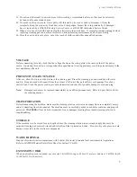
Page 6: ...ing pad Rinse the cleaning pad and wand tip with water and dry Clean dust and dirt deposits from the exterior of the unit Keep all airflow vent openings free of any obstructions Clean the power cord to prevent deterioration and check for possible damage to cord and plug Note Damaged cords must be replaced immediately by qualified personnel only Refer to Spare Parts List for the ordering number TRA...

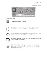
Page 7: ...or unit power ON Indicator for wand tip power ON Indicator for LOW solution level Manual pumping mode Automatic pumping mode Marking Wand selector Mini Wand selector Cleaning Wand selector Voltage selector III EQUIPMENT CONTROLS III EQUIPMENT CONTROLS 6 III EQUIPMENT CONTROLS ...

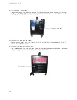
Page 8: ... T filling and reservoir Wand holder Compressed air connector for fume elimination system ON OFF button Accessory outlet Ground connector Control panel III EQUIPMENT CONTROLS Power cord Hand Wand hose electrical and solution supply lines ...

Page 9: ...dous they can be uncomfortable when working in confined areas working in confined areas To activate this feature simply connect a compressed air line 150 PSI max 80 PSI min to the fitting at the To activate this feature simply connect a compressed air line 150 PSI max 80 PSI min to the fitting at the back of the machine The fume elimination system is automatically activated when the ON button is p...

Page 10: ... accessory outlet Select AC for cleaning and DC for polishing Hand Wand selector or or Select this setting when using the Hand Wand attached to the Surfox unit Select AC for cleaning and DC for polishing C VOLTAGE REGULATOR SWITCH Voltage selector Select a lower voltage for cleaning on delicate surfaces mirror finish Select a higher voltage for thicker plates The selector controls the voltage for ...

Page 11: ... until the OFF button is pressed E INDICATOR LIGHTS Power ON indicator ndicator ndicator Green light is on when the unit is plugged in and the main power switch is turned on Hand Wand power ON indicator The yellow light goes ON when the Hand Wand ON button is pressed and there is power to the tip Power to the tip is OFF when the Hand Wand OFF button is pressed Low solution level indicator When sol...

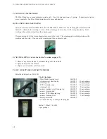
Page 12: ...x 2 5mm hexagonal key for changing Tungsten cleaning tips B FILLING THE RESERVOIR Fill the reservoir in the back of the machine with Surfox T solution The reservoir holds 1 9L of Surfox T solution C MOUNTING A CLEANING PAD 11 Squeeze and insert clamp ring Insert cleaning pad with symbol facing up Firmly press in Tungsten tip Remove tip with installed pad and retaining ring 1 2 3 4 Reservoir V V V ...

Page 13: ... PLUGGING IN THE POWER CORD When an extension cord is needed use wire size 14 AWG for up to 50 feet 15 meters and size 12 AWG for 50 to 100 feet 15 to 30 meters F PLUGGING IN THE GROUND CLAMP Plug the ground clamp at the front of the unit Attach the clamp to the work piece being cleaned The cleaning and passivating process will not work if the part is not properly grounded 12 V V V START UP PROCED...

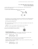
Page 14: ... voltage for mill finish parts or thick plates When working on delicate surfaces mirror finish or very thin gauge lower the voltage Example Mill finish 14 gauge 26 volts Polished finish 16 gauge 18 volts Mirror finish 16 gauge 12 volts WARNING If uncertain of the material type start at a lower voltage and increase as necessary If the voltage is too high it can alter the surface by leaving a white ...

Page 15: ...Hand Wand ON button Make sure the cleaning pad is saturated with d passivate press the Hand Wand ON button Make sure the cleaning pad is saturated with d passivate press the Hand Wand ON button Make sure the cleaning pad is sat Surfox T solution before starting to work If the cleaning pad is too dry it will wear prematurely Start working when solution drips from the cleaning pad Do not press hard ...

Page 16: ...the surface of the finish TIP When using the polishing mode DC use plenty of Surfox T solution B SELECTING THE PROPER VOLTAGE SETTING Recommended voltage settings AC mode for cleaning and passivating Use higher voltage for mill finish parts or thick plates When working on delicate surfaces mirror finish or very thin gauge lower the voltage Example Mill finish 14 gauge 26 volts Polished finish 16 g...

Page 17: ...9 1 Remove any excess Surfox T solution using a soft clean cloth 2 Spray Surfox N on the surface 3 Wipe dry with another soft clean cloth F LIST OF SUPPLIES AND PART NUMBERS Mini Wand kit part no 54 B 033 The kit includes 1 Mini Wand cleaning torch 48 R 285 1 stainless steel cleaning tip 54 B 021 10 per package 1 cleaning pad 54 B 001 10 per package 1 PTFE clamping ring 54 B 002 10 per package 1 c...

Page 18: ...TAGE TYPE AC or B SELECTING THE VOLTAGE TYPE AC or DC AC for marking on stainless steel DC for marking on aluminum C SELECTING THE PROPER VOLTAGE SETTING C SELECTING THE PROPER VOLTAGE SETTING The voltage is automatically fixed at 12V in AC or The voltage is automatically fixed at 12V in AC or DC mode You do not need to set the voltage when selecting the DC mode You do not need to set the voltage ...

Page 19: ... cardboard and keep in a dry place E MARKING WAND SUPPLIES AND PART NUMBERS Marking kit part no 54 B 013 18 The kit includes 1 Marking Wand with 2 O rings 54 B 061 10 Marking pads 54 B 062 10 per package 1 Surfox M 350ml 54 B 053 1 black power cord 54 B 063 1 solution container 54 B 065 5 temporary stencils 54 B 064 100 per package 1 sample custom stencil VIII VIII VIII USING THE MARKING WAND OPTI...

Page 20: ...ons for neutralizing Surfox T cleaning solution 1 Remove any excess Surfox T solution using a soft clean cloth 2 Spray Surfox N on the surface 3 Wipe dry with another soft clean cloth For more information about this product refer to MSDS S 03E WARNING WARNING Be sure to wipe off all excess Surfox T from the surface and neutralize otherwise the inorganic salt from the phosphoric acid will adhere to...

Page 21: ...er 54 B 017 To be used with cleaning pad 54 B 023 and narrow clamp ring 54 B 020 OR To be used with cleaning boot 54 B 007 for internal corners Narrow Tungsten Insert 60º Narrow Tungsten Insert 60º Narrow T For narrow internal surfaces and corners Part number 54 B 018 To be used with cleaning boot 54 B 008 It is easier to get into tight internal corners with the 60º insert than with the standard 9...

Page 22: ... one soft external layer which is soft so that it will not damage or scratch the work piece during the cleaning operation For longer life remove the cleaning pad and neutralize with Surfox N at the end of each working day Cleaning pads are available in two 2 sizes Cleaning pad For large flat surfaces and external angles Part number 54 B 001 To be used with tungsten insert 48 R 133 and clamp ring 5...

Page 23: ...p around the insert they avoid short circuits arcing Several shapes and sizes are available Cleaning boot For large flat internal surfaces or angles Part number 54 B 005 To be used with tungsten insert 48 R 133 Narrow Cleaning boot For narrow flat internal surfaces or angles Part number 54 B 007 To be used with tungsten insert 54 B 017 Cleaning boot 60º For large internal corners or angles Part nu...

Page 24: ...specially formulated phosphoric acid cleaning solution designed to be used only in Walter Surfox cleaning systems Surfox T Electrolyte cleaning solution 1 5L bottle Part number 54 A 005 4 x 1 5L bottles per case WARNING Do not reuse Surfox T solution after it has gone through the Surfox unit for cleaning Used solution loses its cleaning effectiveness while the waste liquid can become contaminated ...

Page 25: ...es above 10 Amps the machine automatically shuts down B INTERNAL TEMPERATURE To protect the internal components of the machine there are temperature sensors inside the machine If the operating temperature is too high the machine will shut down and restart by itself when the temperature reaches an acceptable level There is an internal fan inside the machine to keep all the components cool WARNING T...

Page 26: ...her way continually reversing direction An AC voltage is continually changing between positive and negative Direct Current DC Direct Current DC always flows in the same direction but it may increase and decrease A DC voltage is always positive but may increase and decrease 25 XI SAFETY FEATURES ...

Page 27: ... Oxide layer to be removed Before Cleaning and passivation is perfect Cleans every crack in the material After Microscopic view of the material Before After Oxide layer to be removed Cleaning and passivation is perfect Cleans every crack in the material Alteration of the material due to the DC setting Microscopic view of the material 26 XI SAFETY FEATURES ...

Page 28: ...The contaminated areas do not conduct electricity If there is no conductivity in the material the Surfox system cannot work If there are two 2 welds on top of the other the structure of the material has been seriously altered These areas may not be cleaned The quality of the weld is critical The better the weld the easier it will be to clean 27 XI SAFETY FEATURES ...

Page 29: ...50 60 Hz OUTPUT VOLTAGE 10 30 V AC DC INPUT CURRENT 6 Amps OUTPUT CURRENT 10 Amps AC DC MAX OUTPUT VOLTAGE 33 V AC DC DIMENSIONS 470mm x 380mm x 250mm 18 5 x 15 x 9 75 RESERVOIR CAPACITY 1 9 L WEIGHT 16 8 kg 37 lbs INPUT AIR PRESSURE 150 PSI max 80 PSI min 28 XII TECHNICAL DATA ...

Page 30: ...nty written or verbal is authorized In no event shall WALTER be liable for any indirect incidental or consequential damages from the sale of the WALTER be liable for any indirect incidental or consequential damages from the sale of the WALTER product This disclaimer applies both during and after the term of this warranty This warranty gives you specific rights The provisions contained in this warr...

Reviews: