


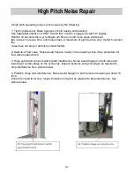


L
ift Cylinder Replacement
Supplement to WDV Cylinder Replacement Instructions for Passengers Side Cylinder Only
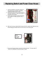
When replacing the passengers side cylinder on an WDV liftgate please note there is a
pressure compensating flow control valve located at the top of the passengers side cylinder.
Older models liftgates have external Pressure compensating flow valves, as seen in photo 1,
and newer liftgates have internal flow valves as seen in photo 2.
On all 3500 lb and 4400 lb liftgates the internal pressure compensating valve is already
installed on your cylinder. You do not need to install the external flow control valve. Attach the
hoses directly to the 3/8 JIC fitting on the cylinder. Use the adaptor provided in the kit to screw
into the cylinder and attach the hose directly back to the adaptor on the cylinder.
On 5500 lb and 6600 lb models the flow control valve is not pre installed.
Please note that on these models we have provided fitting so that you can incorporate either
pressure compensating valve.
Internal valve note: If you have the internal compensating valve, you will need to use a 3/16
allen wrench to remove the old pressure compensating valve from the cylinder and insert it into
the new cylinder. Install the fittings from the old cylinder on the new cylinder.
External Valve note: With the external pressure compensating valves you will need to use one
of the adaptors provided in the kit to re-use the external valve. The adapter used on the old
cylinder may not be the same thread as the new one. Install the adapter provided in the
cylinder kit into the cylinder port and install the flow control and 3/8 JIC fitting onto the adapter.
Reattach hoses.
Picture 1
Picture 2
37
Summary of Contents for WDV
Page 15: ...Electric Hydraulic Flow Schematics Power Up S4 Valve Coil activated for Up function 15...
Page 19: ...Electric Hydraulic Schematics Built from 4 09 thru 10 11 Single pump Motor Single Relay 19...
Page 21: ...Electric Hydraulic Schematics Built from 10 11 Single Pump Motor Dual Relay 21...
Page 23: ...Work Light Electrical Hydraulic Schematic 23...
Page 28: ...28...
Page 29: ...29...
Page 30: ...30...
Page 31: ...31...
Page 48: ...Notes 48...


