17
MOD.
.................................................................................................................................
9011 HD
...
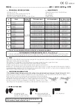
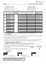
TECHNICAL SPECIFICATIONS
...
NOZZLE
Ø
:
1.5 - 1.9 - 2.2 - 2.5
...
AIR CONSUMPTION:
220 - 240 Lt./min (7.8 - 8.5 CFM)
...
USE
...
ADVICE FOR CORRECT USE
...
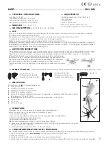
FORM OF THE FAN
...
DESCRIPTION
...
OPERATIONS
...
TANK DEPRESSURISATION SAFETY PROCEDURE
...
ADJUSTMENTS*
- Air fitting: G 1/4” M
- Maximum air pressure: 5 bar (73 psi)
- Maximum tank pressure: 1.5 bar (22 psi)
- Safety valve trip pressure: 1.8 bar (26 psi)
- Working pressure: 2.5-3.0 bar (36-43 psi)
- Fan: Fully open
- Air: Fully open
- Product: 3.5-4.5 turns
*Since spray guns are pressurised, the
recommended regulations are fully indicative.
Spray guns int the 9000 HD series have been designed for the application of finishing colours in all those sectors requiring
high quality finishing and low fumes emission.
The instrument is not suitable for use with abrasives or products containing acids or petrol of any kind.
To obtain the best results, the following instructions must be followed carefully:
1
. When possible, use an air pipe with a minimum internal section of ø 8 mm (0.3”).
2.
Make sure the compressed air used is perfectly filtered removing all water, oil or other impurities (for example, by installing
an Asturomec filter regulator ref. 61131 and Asturomec coalescent microfilter ref. 61201, or by the more complete and efficient
WALCOM TD
3
PRO multifunctional filter and heating unit).
1. The distance between the spray gun and the surface to be painted must be set between 150 and 200 mm (5.9”- 7.9”).
If the spray gun is working at too low a pressure and at too high a distance, il will not perform to the best of its capacity.
2.
The jet from the spray gun must always be perpendicular to the surface being
painted and the paint must be applied in horizontal strokes. Any eventual shift from
this position when spraying will result in an uneven application of the paint layer.
3.
Correct viscosity of the paint is between 15 and 25 sec. Coppa Ford n. 4.
These values depend on the application in question and the measure of the nozzle
in use.
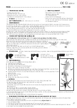
Adjust the air pressure, product quantity and spray aperture until obtaining a regular imprint as in fig. C
- Air pressure too low
- Product viscosity too high
- Quantity of product too high
- Air pressure too high
- Product viscosity too low
- Quantity of product too low
- Regular jet
With reference to
fig.1
, the essential parts are:
1
- spray gun air inlet;
2
- atomization air pressure regulator;
3
- atomization air regulation hand wheel;
4
- internal tank pressure regulator;
5
- internal tank pressure regulation hand wheel. The regulator is calibrated. When fully open, internal
tank pressure is 1.5 bar (22 psi);
6
- tank safety valve; it trips when internal tank pressure reaches 1.8 bar (26 psi);
7
- HD tank cup;
8
- HD tank lid;
9
- HD tank air hose.
WARNING! The HD spray gun version operates with a pressurised tank.
Before connecting the spray gun to the compressed air supply:
- close the hand wheel (
5
);
- make sure the hose (
9
) is correcting inserted in the regulator (
4
) and lid (
8
) fittings;
- fill the tank (
7
) with the product to be sprayed;
- tightly screw the lid (
8
) onto the cup (
7
);
After connect compressed air to the air inlet (
1
), proceed as follows:
A – slowly open the hand wheel (
5
) to pressurise the tank. The higher the product viscosity, the higher
the pressure must be in the tank;
B – adjust atomization air pressure to 2.5 – 3.0 bar (36-43 psi).
The procedure below must always be followed before dismantling and cleaning the spray gun and before topping up product:
1 – make sure the spray gun is
disconnected
from the compressed air supply system
2 - close the faucet (
5
)
3 – aim the spray gun nozzle into an electrically grounded metallic container
4 – pull the lever to release over-pressurised product until the paint flow stops; at this point, the lid can be safely unscrewed (
8
).
1
2
3
4
5
6
7
8
9
fig.1
C
17
Summary of Contents for Asturomec 9011 sp HVLP
Page 53: ...53 1 2 ATEX 0 85 A Asturomec 90109 W...
Page 54: ...54 43 C UNI EN 1953 5 4 85 C TMA TMA 90109 W...
Page 66: ...Note...
Page 67: ...Note...


