background image

FX85, FX110, FX140
PTO Skidding Winch

Attaching Winch to Tractor

23

4.4  Installing PTO Shaft

The implement must be mounted to the tractor, and fully lowered 
to the ground. Make sure tractor is shut off with parking brake 
applied. 

Check to make sure the shielding on the PTO shaft is in good 
condition and able to turn freely, independent of the PTO shaft. 

Make sure the PTO yoke ends are clean. Adding a small amount 
of lubricant on the splines can help them slide on.

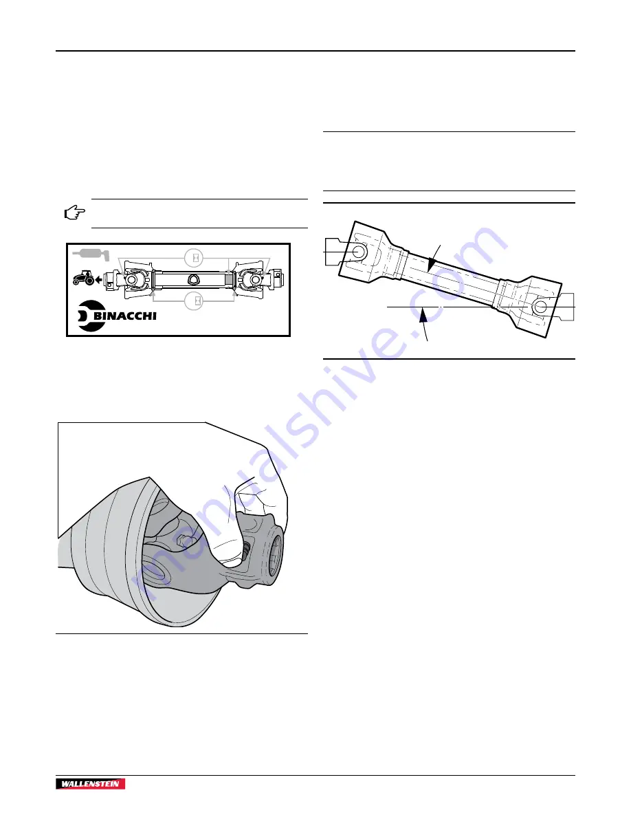
A decal on the shielding indicates the tractor-
end of the driveshaft.

Via Che Guevara, 38

42045 LUZZARA (RE) ITALY

50

8

01655

1. 

Install the PTO shaft on the implement. Press the locking 
pin button and push the shaft end onto the input PTO. 
Connect the safety chain to the implement so that the 
shielding does not turn during operation.

00866

Fig.  21 – 

Locking Pin Button

2. 

Slide out the end of the PTO shaft up to the tractor output 
PTO, aligning the two shaft splines. Press the locking pin 
button and push the shaft end onto output PTO.

3. 

Once started, slide the shaft all the way on. You might 
hear a click and your button should retract to the original 
position. 

4. 

To check that the shaft lock is fully seated, pull back on the 
shaft with your hands off the button.

5. 

Start the tractor and raise / lower the attachment to check 
clearances. A correctly sized shaft should never bottom out 
or come apart. 

IMPORTANT!  Check driveshaft alignment. During operation, 
the working angle should not be greater than 15° between 
the tractor and the implement. Misalignment can cause 
premature wear and eventually failure.

15°

01650

Fig.  22 – 

Driveshaft Alignment

6. 

Check the rotation direction. A decal on the machine 
indicates correct rotation.

Summary of Contents for FX Series

Page 1: ...OPERATOR S MANUAL PTO driven Log Skidding Winch FX Series Part Number Z97090_En Rev May 2021 ...

Page 2: ... Option Synthetic Rope Option Safe efficient and trouble free operation of this Wallenstein product requires that anyone using or maintaining the machine reads and understands the Safety Operation Maintenance information contained within this Operator s Manual Units of measurement in Wallenstein Equipment technical manuals are written as US Customary SI metric Keep this manual handy for frequent r...

Page 3: ...haft 23 5 Controls 24 5 1 Winch Clutch 24 5 2 Winch Drum Lock 24 5 3 Forged Cable End 24 5 4 Keyhole Sliders 25 5 5 Keyhole Slots 25 5 6 Choker Chains 26 5 7 Synthetic Chokers 26 5 8 Lower Snatch Block 26 5 9 Trailer Hitch 27 5 10 Safety Screen 27 5 11 Remote Winch Control 27 6 Operating Instructions 31 6 1 Pre start Checks 31 6 2 Machine Break In 32 6 3 Winch Safety 32 6 4 Winching Logs 33 6 5 Sk...

Page 4: ...horoughly instructed the buyer on the equipment care adjustments safe operation and applicable warranty policy and reviewed the manuals Dealer Address City State Province ZIP Postal Code Phone Number 1 2 1 Dealer Inspection Report Check condition of winch rope spooled correctly Drive chain tension checked PTO shaft telescopes is greased Shield turns Fasteners tight Grease zerks pivot points lubric...

Page 5: ...ct Information Here Model Serial Number VIN NLV MODEL Manufactured by Wallenstein Equipment Inc 7201 Line 86 Wallenstein ON N0B2S0 Canada TYPE OF VEHICLE TYPE DE VEHICLE TRA REM GAWR PNBE KG GVWR PNBV KG DIMENSION RIM JANTE E R I T PNEU COLD INFL PRESS PRESS DE CONFLA A FROID PSI LPC THIS VEHICLE CONFORMS TO ALL APPLICABLE STANDARDS PRESCRIBED UNDER THE CANADIAN MOTOR SAFTEY REGULATIONS IN EFFECT ...

Page 6: ...ary in the number of panels This type of decal explains the operation of a control Product Decals indicate machine model and serial number and other important information VIN NLV MODEL Manufactured by Wallenstein Equipment Inc 7201 Line 86 Wallenstein ON N0B2S0 Canada TYPE OF VEHICLE TYPE DE VEHICLE TRA REM GAWR PNBE KG GVWR PNBV KG DIMENSION RIM JANTE E R I T PNEU COLD INFL PRESS PRESS DE CONFLA ...

Page 7: ...tices CAUTION Indicates a potentially hazardous situation that if not avoided may result in minor or moderate injury It may also be used to alert against unsafe practices IMPORTANT To avoid confusing equipment protection with personal safety messages a signal word IMPORTANT indicates a situation that if not avoided could result in damage to the machine 2 3 Why is SAFETY important Three Big Reasons...

Page 8: ...tion and or safety and could affect the life of the equipment DO NOT allow riders during transport DO NOT risk injury or death by ignoring good safety practices 2 5 Operating Safety Understand the meaning of the safety signs on the machine Keep them clean Replace them if they become damaged Never operate this winch with guards or shields removed The manufacturer has designed this skidding winch to...

Page 9: ... to acquaint yourself with it If this machine is used by any person other than yourself or is loaned or rented it is the machine owner s responsibility to make certain that prior to using the operator reads and understands the owner s manual is instructed in safe and proper use of the equipment understands and knows how to perform the Safe Condition procedure Train all new personnel and review ins...

Page 10: ...at shows signs of swelling wear leaks or damage before it bursts Do not bend or strike high pressure lines tubes or hoses or reinstall them in a bent or damaged condition Check to make sure hydraulic hoses are not worn or damaged and are routed to avoid chafing Never adjust a pressure relief valve or other pressure limiting device to a higher pressure than specified ...

Page 11: ... Safety Usage and Maintenance information presented in this manual Do not use or allow anyone else to use this winch until such information has been reviewed Annually review this information before the season start up Make these periodic reviews of SAFETY and OPERATION a standard practice for all of your equipment We feel that an untrained operator is unqualified to use this machine A sign off for...

Page 12: ...or particular function related to that area that requires your SAFETY AWARENESS Think SAFETY Work SAFELY IMPORTANT If parts are replaced that have safety signs on them new signs must be applied Safety signs must always be replaced if they become damaged are removed or become illegible Safety signs are included in the product decal kit available from your authorized dealer Decals are not available ...

Page 13: ...FX85 FX110 FX140 PTO Skidding Winch Safety Safety 13 Fig 3 FX Series Safety Decal Placement 00577 5 6 7 8 ...

Page 14: ...away from driveline while it is rotating 3 Warning Risk of injury when servicing or repairing this machine Disconnect the driveline before working on this machine 4 Warning Concealed hydraulic fluid connection under pressure Use caution when removing panels or guards Do not check for leaks with your hand or fingers when the system is pressurized Serious injury can result R models only equipped wit...

Page 15: ...afety signs are included in the product decal kit available from your authorized dealer Decals are not available separately 2 10 1Replacing Damaged Safety Signs Always keep safety signs clean and legible Replace safety signs that are missing or have become illegible Parts that were replaced with a safety decal on them must also have the safety sign replaced Replacement safety signs are available f...

Page 16: ... is familiar and comfortable with the machine they can proceed with the work Do not allow untrained operators to use the machine They can endanger themselves and others or damage property and the machine 3 4 Job Site Familiarization It is the responsibility of the operator to be thoroughly familiar with the work site prior to starting Prevent the chance or possibility of problems or accidents by n...

Page 17: ... Models 4 Remote Control Receiver R Models 5 Safety Screen 6 Hydraulic Hoses R Models 7 Drum Lock Rope green 8 Clutch Adjuster 9 Top Cable Pulley 10 Winch Clutch Rope white 11 PTO Shaft 12 Chain Tow Bar 13 Draw Bar FX85 R FX110 R FX140 R models 14 Key Hole Sliders FX85 R FX110 R FX140 R models 15 Snatch Block 16 Wire Rope Synthetic Rope on S Models 17 Support Legs 18 Anchor Blade 3 6 Winch Compone...

Page 18: ...re equipped with the remote winch control and require 1 2 gpm hydraulic flow and a 12 VDC power source Make sure there is enough room and clearance to safely back the tractor up to the winch 1 Move the tractor drawbar forward for clearance if required 2 Place the tractor lift arms in their full sway position Remove the hitch pins from the winch 3 At the slowest speed back the tractor up keeping it...

Page 19: ...trol and a receiver mounted on the winch For the remote to function the following electrical and hydraulic connections to the winch must be made Electrical Connection A 12 VDC 1 5 amp power source is required from the tractor electrical system The white wire from the receiver should be connected to positive black to ground Connectors are not supplied on the wire ends Wire ends are supplied bare to...

Page 20: ...es in the manual and follow all safety signs on the machine CAUTION Wear suitable eye protection when cutting steel tubes Remove the PTO shaft and mount the attachment on the tractor three point hitch 1 Start the tractor and raise the three point hitch up off the ground until the machine s input shaft is level with the tractor PTO output shaft This is the shortest distance between the input and ou...

Page 21: ...be off at the mark 10 Using the cut off length of plastic tube to mark the remaining cuts repeat this process for BOTH PTO shaft halves Place the end of the steel shaft to be cut off in a vice so it is easier to control your cut 11 Remove the burrs from the edges of the steel shaft that were cut Clean the steel shaft halves 12 Grease the inner tube so the tube halves slide together easier 00868 Fi...

Page 22: ...he locking collars on each input Subtract 2 inches 50 mm from this measurement Call this measurement B L 2 50 mm B 00944 L Fig 18 Measurement B 4 If the collapsed length A is longer than measurement B from Step 3 the PTO shaft must be shortened 5 Subtract B from the uncut PTO shaft measurement A A B The result is how much BOTH halves of the PTO shaft need to be shortened Call this value C A B C 00...

Page 23: ...ment so that the shielding does not turn during operation 00866 Fig 21 Locking Pin Button 2 Slide out the end of the PTO shaft up to the tractor output PTO aligning the two shaft splines Press the locking pin button and push the shaft end onto output PTO 3 Once started slide the shaft all the way on You might hear a click and your button should retract to the original position 4 To check that the ...

Page 24: ...ply on the green winch lock rope 2 The latch engages on the cogged winch drum While the tractor is moving forward pressure is applied to the latch and it remains engaged so the rope can be relaxed With the winch drum locked and the machine can tow or pull a load 2 00587 Fig 24 Drum Lock NOTE The latch may disengage if the tractor stops moving forward 5 2 2 Disengaging Drum Lock To disengage the dr...

Page 25: ... chain to the winch rope 00498 Fig 27 Keyhole Sliders Synthetic rope option has two keyhole sliders with a forged hook end 01435 2 1 Fig 28 Synthetic Rope 1 Keyhole Sliders 2 Forged Hook End IMPORTANT If the winch is equipped with a synthetic rope always use a choker chain NEVER wrap the rope around the log or hook the forged end back onto the rope Damage to the rope results that is not covered by...

Page 26: ...le damage Replace if kinked frayed has knots cuts or any broken strands Failure to replace could result in breakage WARNING Synthetic rope that fails under tension can snap back with great force causing injury or death Avoid sudden jerks quick starts or stops Start slowly and smoothly Replace if kinked badly frayed has knots cuts or broken strands W095 Push the probe end of the choker under the lo...

Page 27: ...rame The trailer hitch is held in with a pin and clip 00595 Fig 33 Trailer Hitch 5 10 Safety Screen Each machine is equipped with a safety screen that protects the operator from flying chips twigs branches and rope recoil in the unlikely event of breakage when skidding or winching Always keep the safety screen in good condition 00596 Fig 34 Winch Safety Screen 5 11 Remote Winch Control FX85R FX110...

Page 28: ...old to activate the winch retract the cable The transmitter sends a signal to the receiver once pressed The winch stops when the button is released LED Indicator lights 3 These LEDs indicate system status The center LED is green during normal operation When 10 of battery life remains it lights red The left and right hand LEDs are red and come on to indicate a system error Power Off Button 4 Push t...

Page 29: ...the ON button until the green LED turns on then release The green LED flashes rapidly when communication has been established with the receiver It flashes slowly if the receiver is off or there is no communication between the transmitter and receiver Press and hold the UP arrow to retract the winch cable Release the button to disengage the winch and stop the cable retracting 00833 Fig 38 Remote Tr...

Page 30: ...ansmitter are now synchronized If no transmitter is found within approximately 10 seconds the receiver exits to normal operation 5 11 7Erasing all Transmitters from the Receiver In the event it is necessary to erase a transmitter from the receiver follow these steps 1 Press the receiver Function F button The function LED lights red 2 Press the receiver Select S button Keep pressed at least 4 secon...

Page 31: ...an spin freely Check and lubricate the PTO shaft following the schedule outlined in the Maintenance section Check the condition of the winch rope for visible damage Replace if kinked frayed has knots cuts or any broken strands Failure to replace could result in breakage For synthetic rope see page 42 Check the condition of the winch clutch Check that all bearings turn freely Replace any that are r...

Page 32: ...ecoil may cause injury or death to a person in its path Do not risk a rollover by exceeding a winching angle of 25 from the centerline of the tractor If unsure of winch angle reposition tractor or use a snatch block Whenever possible winch in line with the tractor Do not allow anyone within 20 ft 6 m of logs when winching Logs can roll in unpredictable ways Choose a flat solid skidding route for t...

Page 33: ...gine 4 Pull the rope out to the load Avoid twists in the rope 5 Attach the choker chain to the log and to the rope end 6 Start tractor engine and engage PTO Set throttle to 1 4 to 1 2 range Winch speed is based on tractor PTO speed and can operate up to 540 rpm 7 Stand to the side of the winch and pull firmly on the clutch rope to retract the rope and load IMPORTANT Keep a steady firm pull on the ...

Page 34: ...n operating the winch always stay at least 10 ft 3 m to the side of the of machine Lower three point hitch and winch frame to the ground when winching The weight of the load helps push the blade into the ground anchoring the winch and the tractor Winching in from the top pulley lifts the end of the log up so it tends to dig into the ground less Always wind rope in under load Rope does not wind in ...

Page 35: ...gs pull slightly on the white top rope to release the drum lock Points to Remember When skidding logs route the rope through the lower pulley so the tractor is more stable Skidding from the top of the mast could cause a tip over Raise winch frame up above the ground to clear obstacles when skidding Use a log chain or choker chain to connect to the winch cable Do not use a rope or strap to prevent ...

Page 36: ...ng Winch 36 00600 Fig 47 Winch Log over Rough Ground Tractor Gets Stuck Unlock the winch to let the rope drum freespool Drive the tractor to firm ground then winch the load back in If the tractor cannot be moved drop the load and winch the tractor out ...

Page 37: ... diesel fuel Use regular cleanser Always use proper tools in good condition Make sure a procedure is understood before beginning 7 1 1 Hydraulic System Safety Make sure that all the components in the hydraulic system are kept clean and in good condition Make sure all connections are tight and that lines hoses and couplings are not damaged before applying pressure to the system Do not use a hand to...

Page 38: ... gun for all greasing Pump one shot of grease slowly into each fitting Wipe grease fitting with a clean cloth before greasing to avoid injecting dirt and grit If fittings do not take grease remove and clean them thoroughly Replace grease fittings as necessary IMPORTANT Do not over grease Pumping more than one shot from a grease gun into the bearings can push the grease out of the seals Doing that ...

Page 39: ...in Lubrication Lubricate the drive chain every 50 hours of operation A chain operating in a dry condition can wear excessively leading to premature failure Remove the lower protective shield on the front side of the winch Spray or brush oil onto the lower drive chain A good quality penetrating oil such as WD40 works well to reach the pin and bushing joints IMPORTANT Avoid getting oil on the clutch...

Page 40: ...tall the new chain 3 To set the chain to maximum tension turn out the adjusting nut on tension bolt within 1 4 6 mm from end of tension bolt 7 6 Clutch Adjustment Adjust the clutch using the following method if it begins to slip or goes out of adjustment 00604 1 2 Fig 51 Clutch Adjustment 1 Jam Nut 2 Socket Head Capscrew Procedure 1 Loosen the three jam nuts on the front side of the winch 2 Turn s...

Page 41: ... the arm to release the brake When the rope is no longer being spooled on the spring pulls the arm back and engages the brake The brake must be set to stop the drum from freewheeling when the rope is not being pulled out to avoid tangling Remove lower protective shield from the front side of the winch to access brake adjustment 00606 1 2 3 4 5 6 Fig 52 Winch Brake 1 Adjuster Bolt 2 Jam Nut 3 Drum ...

Page 42: ...art slowly and smoothly Replace if kinked badly frayed has knots cuts or broken strands W095 Rope inspection It is a good idea to check the entire rope for wear and re spool it neatly after every use Check the winch rope for any cut strands fraying parts abrasion or heat damage from the winch After use all winch lines will get a little fuzzy from abrasion This is normal but if an entire strand is ...

Page 43: ...Rope When dirt and grit become lodged in between the strands of the winch line they cause abrasion to the fibers when the winch line is put under a load Over time this can cause a breakdown in the integrity and strength of the rope Wash winch rope if it gets dirty by unspooling the entire line from the winch and lay it on a clean surface Once the line is laid out rinse it well with water from a ho...

Page 44: ... by resting it on wood blocking 4 Wash the machine to remove all dirt mud and debris Inspect all rotating parts and remove any entangled material 5 Check the condition of chain and sprockets Replace or adjust as required 6 If the winch cannot be stored inside cover with a waterproof tarp 00613 Fig 56 Storage Position 7 12 Transporting 00612 Fig 57 Winch Attached Comply with local laws governing sa...

Page 45: ... function Cable does not pull out Winch drum lock engaged Disengage winch lock Cable jammed Disengage winch or release brake and pull cable out Rewind cable onto the spool Check winch brake Slow cable retraction PTO shaft speed too slow Increase PTO speed maximum 540 rpm Clutch slipping Pull harder on clutch rope Adjust Clutch Clutch brake pads worn Replace Reduce load Grease or oil has got on clu...

Page 46: ... Drive sprocket misaligned PTO shaft too long Check that PTO shaft is the correct length Front end of tractor comes off ground when winching Tractor too light in front Add front end weights Tractor slides backwards when winching Parking brake not applied Apply parking brake Winch blade not fully lowered enough to anchor firmly in the ground Lower the winch all way to the ground ...

Page 47: ... 5 mm 7 16 11 mm 1 2 12 7 mm Maximum Input Torque 265 lbf ft 360 N m 351 lbf ft 476 N m 450 lbf ft 610 N m Maximum Bare Drum Pull 8 553 lb 3 879 kg 11 130 lb 5 048 kg 14 053 lb 6 374 kg Maximum Full Drum Pull 2 992 lb 1 357 kg 3 673 lb 1 666 kg 4 733 lb 2 146 kg Hydraulic Flow Required for Remote Control R and RS models only 1 2 gpm 3 8 7 6 Lpm Synthetic Winch Rope 7 16 x 200 ft with Hook Chain En...

Page 48: ...ker increase torque values by 5 NOTE Bolt grades are identified by their head markings Imperial Bolt Torque Specifications Bolt Diameter Torque Value SAE Gr 2 SAE Gr 5 SAE Gr 8 lbf ft N m lbf ft N m lbf ft N m 1 4 6 8 9 12 12 17 5 16 10 13 19 25 27 36 3 8 20 27 33 45 45 63 7 16 30 41 53 72 75 100 1 2 45 61 80 110 115 155 9 16 60 95 115 155 165 220 5 8 95 128 160 215 220 305 3 4 165 225 290 390 400...

Page 49: ...tor body and tighten the swivel nut with the second Torque to values shown If a torque wrench is not available use the FFFT Flats From Finger Tight method Hydraulic Fitting Torque Tube Size OD Hex Size Across Flats Torque value Flats From Finger Tight Inches Inches lbf ft N m Flats Turns 3 16 7 16 6 8 2 1 6 1 4 9 16 11 12 15 17 2 1 6 5 16 5 8 14 16 19 22 2 1 6 3 8 11 16 20 22 27 30 1 1 4 1 6 1 2 7...

Page 50: ... Synthetic Choker Self releasing Directional Pulley When obstacles prevent direct winching or to prevent damage to other trees the Wallenstein self releasing directional pulley should be used The pulley releases the rope when the keyhole slider reaches it Fig 61 Self releasing Directional Pulley Chain Saw Holder The chain saw holder bolts to the side of the winch Fig 62 Chain Saw Holder ...

Page 51: ...iginal purchase receipt with any claim This warranty does not cover the following 1 Normal maintenance or adjustments 2 Normal replacement of wearable and service parts 3 Consequen al damage indirect damage or loss of profits 4 Damages resul ng from Misuse negligence accident the or fire Use of improper or insufficient fuel fluids or lubricants Use of parts or a ermarket accessories other than genuine ...

Page 52: ...ning 16 Forged Cable End 24 G Grease Points 38 H Hand held Transmitter 28 Hearing loss 9 Hydraulic Fitting Torque 49 Hydraulic System Safety 37 I Informative Labels 6 Installing PTO Shaft 23 I O Button 28 K Keyhole Sliders 25 Keyhole Slots 25 L Lower Snatch Block 26 M Machine Break In 32 Machine Specifications 47 Maintenance Schedule 38 100 hours or Annually 38 As required 38 Every 50 hours or wee...

Page 53: ...off form 11 Sizing PTO Shaft 20 Skidding 35 Skidding over Rough Ground 35 Specifications 47 FX85 FX85R FX85S FX85RS 47 FX110 FX110R FX110S FX110RS 47 FX140 FX140R FX140S FX140RS 47 Hydraulic Fitting Torque 49 Storage 44 Synchronize Transmitter and Receiver 29 Synthetic Chokers 26 Synthetic Rope Cleaning 43 Handling 42 Rope inspection 42 Strength 42 Synthetic Rope Precautions 25 26 32 Weather 43 Sy...

Page 54: ......

Page 55: ......

Page 56: ...www wallensteinequipment com ...

Reviews: