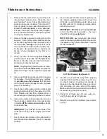
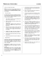
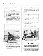
background image

Operating Instructions

43

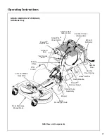
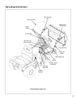
Power Dump Components

Grass Catcher

Cable
Guide

Catcher Door

Gas Spring

Catcher Door

Cable Rod

Guide

Cable Assembly

Actuator Mount

Assembly

Dog Leg

Assembly

Fork

Lift Channel

Door Actuator

Arm

Gas

Spring

Rubber

Bumper

Power Dump

Ram Actuator

Summary of Contents for MT 20.0 HP

Page 1: ...ntenance Instructions Model MT 20 0 25 0 HP Covers Serial Numbers 95 21329 and on Please Read and Save These Instructions Effective Date 08 14 98 For Safety Read All Safety and Operation P N 8000 1 In...

Page 2: ...t be read and understood to help prevent possible injury to the operator or others If anything in this manual is confusing or hard to understand please call our service department at 970 221 5614 for...

Page 3: ...k Installation on Tractor ______ 18 Deck Installation _____________________ 18 Deck Leveling _______________________ 20 PREOPERATING CHECKLIST ____________ 21 Operating Instructions_____________ 24 CO...

Page 4: ..._______ 61 Sharpen Mower Blades ________________ 61 Drive Belts __________________________ 62 Mower Deck Gearbox Oil Seals _________ 63 Spark Plugs _________________________ 63 Fuel Lines and Clamps _...

Page 5: ...main wheels HYDROSTATIC TRANSMISSION transmits and controls power from the ground drive belt to the main drive wheel LEFT HAND LH refers to the left hand side of the tractor when the operator is seate...

Page 6: ...rvice of these components during the limited war ranty period it is important to find a local authorized servicing agent of the component manufacturer Any unauthorized work done on these compo nents d...

Page 7: ...ine 87 Octane Cooling System Capacity Air Cooled Air Cooled ELECTRICAL SYSTEM Battery 12 Volt 35AH 295 CCA 12 Volt 35AH 295 CCA Charging System Flywheel Alternator Flywheel Alternator Charging Output...

Page 8: ...0 8 Infinitely Variable 0 5 0 8 Infinitely Variable 0 5 0 8 Infinitely Variable BLADE DRIVE PTO Shaft Quick Disconnect Rectangular Shaft with Two High Speed U Joints Quick Disconnect Rectangular Shaf...

Page 9: ...erlap Two Blades CW Rotation 22 in 56 cm 2 in 5 cm Center Overlap Two Blades CW Rotation 48 in 122 cm GHS 25 in 64 cm 2 in 5 cm Center Overlap Two Blades Counter Rotate 25 in 64 cm 2 in 5 cm Center Ov...

Page 10: ...Capacity 76 Gallons 335 liters 9 5 Bushels 76 Gallons 335 liters 9 5 Bushels Full Signal Oscillating Vane Switch Mounted on Grass Delivery Spout Triggers Horn Signal Oscillating Vane Switch Mounted on...

Page 11: ...ntrol Rod Adjustment Nut RH Deck Support Arms Transmission Control Rod Adjustment Nut LH Deck Lift Handle Cutting Height Adjustment Deck Caster Wheels Tilt Up Hook Tilt Up Deck Handle Catcher Lift Dum...

Page 12: ...k Mounted Deck Lift Rod Left Hand Drive Wheel Muffler Tailpipe Oil Drain Plug Catcher Door Handle Dump Plate Catcher Door Anti Scuff Roller Oil Filter Tailwheel Fork and Wheels Removable Grass Catcher...

Page 13: ...tcher Support Muffler 20 Amp Fuse Starter Solenoid GHS Blower RH Hydrostatic Transmission PTO Clutch Lever 30 Amp Circuit Breaker RH Transmission Lockout Lever Turbine Precleaner PTO Gearbox Dipstick...

Page 14: ...act your authorized Walker Mower Dealer or call Walker Manufacturing Company at 970 221 5614 BEFORE OPERATING 1 Read and understand the contents of this Owner s Manual before starting and operat ing t...

Page 15: ...d clean up any spilled fuel before starting the engine 11 Never attempt to make any adjustments while the engine is running except where spe cifically instructed to do so 12 The electrical system batt...

Page 16: ...closed Also keep fingers and hands clear of the door frame The door is held closed with springs and the door may slam shut with considerable force 17 In case of a clogged or plugged mower deck or GHS...

Page 17: ...9 Do not change the engine governor settings or overspeed the engine The governor has been factory set for maximum safe engine operating speed 10 Use genuine factory replacement parts Substitute parts...

Page 18: ...low Front Body Latch Release 7820 Rear Cross Member of Front Body 8825 Rear of Grass Catcher Exhaust Screen 5869 Engine Shroud 5855 SAFETY CONTROL AND INSTRUCTION DECALS Safety Control and Instruction...

Page 19: ...27 Gear Axle 5810 1 Deck Gearbox Cover 5807 1 On Engine 6810 Left Side of Operator Seat 8819 SAFETY CONTROL AND INSTRUCTION DECALS Safety Control and Instruction Decals are installed on the machine if...

Page 20: ...o lyte level is low or the battery needs to be charged then 1 Fill each battery cell with drinking water to the bottom of the vent wells 2 Charge battery Refer to Battery Charging in this section Dry...

Page 21: ...stallation 1 Remove the bolt nut axle spacer tube and spacer washers from each deck caster wheel fork NOTE Spacer washers are used only when the optional semi pneumatic deck wheels 8 25 x 2 75 are ins...

Page 22: ...ount and fastening with two 3 8 16 x 1 1 4 in bolts 3 8 16 ESNA nuts and 3 8 in wave spring washers The wave washers fit between the two hinging surfaces Tighten the nuts until the shield moves freely...

Page 23: ...actor and release the ring IMPORTANT To prevent damage to the mower make sure the PTO shaft assembly is securely locked on the tractor with the locking balls fully seat ed in the groove and the ring i...

Page 24: ...easure the distance from blade tip to ground on the front and rear The rear of the blade should be 1 8 to 1 4 in 3 to 6 mm higher than the front of the blade shim the rear or front deck support pins e...

Page 25: ...structions CHECK AND SERVICE ENGINE AIR CLEAN ER SYSTEM Check air restriction gauge to make sure there is no red indication showing Check condition cleanliness and security of the complete air cleaner...

Page 26: ...Refer to CLEANING the GHS Blower in Mainte nance Instructions for blower cleaning information NOTE Mower deck is secured in raised position for cleaning and changing blades by hooking the deck lift r...

Page 27: ...ADJUST MOWER CUTTING HEIGHT IF RE QUIRED Position the hitch pins in the four deck support pins Refer to the Cutting Height Adjustment decal on the deck gearbox cover PERFORM ANY ADDITIONAL PROCEDURES...

Page 28: ...as possible move the choke to the OFF position A warm engine requires little or no choke for starting IMPORTANT Make sure the choke is in the OFF position during normal engine operation running with...

Page 29: ...teering le vers operate only with a backward pulling movement of the lever which causes the drive wheel for that lever to first slow down stop and then reverse with a full backward lever stroke The le...

Page 30: ...e without the engine running e g for ser vice Refer to TRANSMISSION LOCKOUT in this section for operating instructions Lockout Lever Location NOTE The transmission plunger on the side of the transmiss...

Page 31: ...WHEEL STEERING LEVER RIGHT WHEEL STEERING LEVER Reverse Drive Wheel Motion Position FORWARD SPEED CONTROL LEVER FSC Full Forward Ground Speed Position Neutral Park Position Disengaged Position Engage...

Page 32: ...rument Panel This illustration shows the configuration of the switches and indicators located on the instrument panel Hourmeter Voltmeter Oil Pressure Warning Light Over Temperature Warning Light Igni...

Page 33: ...linder head If this light comes on there may be a problem with Engine cooling system material packed into cyl inder head cooling fins clogged air intake screen Low oil level in crankcase Stop the engi...

Page 34: ...checked before further cranking Turn the key to the OFF position and allow a 60 second cool down period between starting attempts Failure to follow these guidelines can damage the starter motor and s...

Page 35: ...erator is completely comfortable handling the ma chine BEFORE ATTEMPTING TO MOW DANGER Keep feet on footrests all times when the machine is moving Beginning Recommendations are Learn operation of the...

Page 36: ...astically short en drive belt life Use only moderate engine speed when engaging the blade clutch 2 Pull the blade clutch lever SLOWLY up to en gage the mower blades IMPORTANT DO NOT engage the blade c...

Page 37: ...brake IMPORTANT The hydrostatic transmissions lock to prevent the mower from rolling freely with the engine stopped However if the mower is parked on a slope it is necessary to ENGAGE the parking BRA...

Page 38: ...lace with the locking cam 3 The mower will freewheel with the levers in the LOCKOUT position The levers must be in the highest position to completely unlock the trans missions Lockout Lever Freewheel...

Page 39: ...ssembly Instructions Use an alternating stripe mowing pattern for best appearance and vary the direction of the stripe each time the grass is mowed to avoid wear patterns in the grass Avoid damage to...

Page 40: ...ody should never be tilted for ward with the deck in the tilt up position This can cause the deck to unhook from the tractor and fall with considerable force potentially causing deck or tractor damage...

Page 41: ...Clutch Rear Discharge Mower Deck Deck Discharge Chute Blower Body Chute Assembly Powerfil Delivery Spout Grass Catcher Catcher Door Spring Catcher Door Exhaust Deflector Exhaust Screen Removable Catch...

Page 42: ...tions NOTE In Autumn when using the GHS mower to vacuum leaves it is recommended to raise the front of the mower deck 2 to 3 notches 1 to 1 1 2 in 25 to 38 mm higher than the rear This will avoid bull...

Page 43: ...nd free of grass and dirt buildup While some degree of material buildup can be tolerated a point is finally reached where the flow of air and grass clippings is restricted NOTE One condition that quic...

Page 44: ...blade clutch engine not running opening the catcher back door and triggering the Grass Pak vane by hand as it oscillates The horn should sound as the switch is moved in both directions The full signa...

Page 45: ...sing the safety latch on the door hinge mechanism with the right hand The safety latch is released by pressing in on the top of the latch Then smoothly close the door working against the spring pressu...

Page 46: ...ens and closes during the dump cycle Hold the toggle switch UP or DOWN to RAISE or LOWER the catcher When the catcher reaches the full raised or lowered position the power ram clutch will make a ratch...

Page 47: ...mp Components Grass Catcher Cable Guide Catcher Door Gas Spring Catcher Door Cable Rod Guide Cable Assembly Actuator Mount Assembly Dog Leg Assembly Fork Lift Channel Door Actuator Arm Gas Spring Rubb...

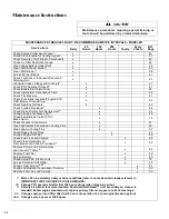
Page 48: ...n Gear Axle x 51 Clean Hydrostatic Transmission Cooling Fins x 60 Clean Engine Cooling Fins x 57 Check Regap Spark Plugs x 63 Change Engine Oil Filter x 46 Check Fuel Lines and Clamps x 63 Check Clean...

Page 49: ...on media and require more frequent cleaning and re placement see following instructions Use the air flow restriction gauge to indicate the need to service the primary air filter Do frequently check th...

Page 50: ...pstick clean the area around the dipstick to keep any dirt or debris out of the engine 3 Remove the dipstick wipe off with a clean rag then reinsert the dipstick into the tube and press all the way do...

Page 51: ...the en gine manufacturer Refer to Specifications in this manual or the engine owner s manual Use the recommended oil viscosity for the expected ambient temperature Oil with the correct vis cosity will...

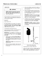
Page 52: ...rottle Control Cable Ends Oil 2 24 Clutch Actuator Push Rod Grease 2 25 PTO Clutch Lever Pivot Grease 1 26 Belt Tightener Pivot Grease 1 PTO Clutch 27 Brake Actuator Rod and Brake Oil 3 Band Pivot Pin...

Page 53: ...Maintenance Instructions LUBRICATION 49 Chassis and Deck Lubrication Points...

Page 54: ...is low add SAE E P Extreme Pressure 90W oil until the oil level is up to sub merges the horizontal shaft in the gearbox shaft parallel to cover plate NOTE In case the gearboxes are completely drained...

Page 55: ...x to avoid oil leakage out of the dipstick standpipe If the oil level is low check the gearbox for any indi cation of an oil leak If an oil leak is noted the gear box will need to be removed and rebui...

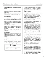
Page 56: ...to Specifications for the proper flu id Any of the listed fluids may be used As soon as there is fluid leaking from around the air bleed plug tighten the plug and fill the reservoir to the COLD level...

Page 57: ...to the COLD level line CLEANING Engine Air Cleaner System There are three main components in the engine air cleaner system a turbine precleaner a Donaldson Radialseal air cleaner and the standard Kohl...

Page 58: ...minating the possibility of dust leaks due to improper filter installation Intake design internal baffling and a Vacuator valve provide dust sepa ration and automatic precleaning action Daily or frequ...

Page 59: ...de of the open end of the filter Replace the filter if any cracks tears or other damage to the sealing surface are noted 6 Use a clean damp cloth and wipe the interior of the air cleaner canister clea...

Page 60: ...recommend clean ing the paper element and reinstalling DO NOT wash the element or use pressurized air to clean as this will damage the element NEVER apply oil to the paper element 1 Unscrew the air cl...

Page 61: ...ed below Every 100 hours inspect and clean the cooling fins more often when operating in extremely dusty dirty conditions Remove the two 2 cooling fin access panels in the engine shroud and clean the...

Page 62: ...of too much buildup on the baffling and housing Tilt Up Decks 1 Raise the deck lock lever handle on each side of the carrier frame and pull out to release car rier frame for tilting action 2 Using the...

Page 63: ...ear of the blower pulley allowing free movement of the blower wheel IMPORTANT With the belt removed the blow er wheel must spin freely Any binding or drag ging of the wheel is an indication of dirt bu...

Page 64: ...on Components NOTE The following inspection is only an exter nal inspection and should be done without dis turbing the filtration components On a daily basis visually inspect the external condi tion o...

Page 65: ...r more often when mowing abrasive type grass or operating on sandy soils Replace blades if worn bent cracked or otherwise damaged refer to REPLACING RE PAIRINGthe Mower Bladesin thissection Use the fo...

Page 66: ...netic Wall Mounted Balancer 7 Mount the blade with wing tips pointing up into the housing Reinstall the blade washer lock washer and nut Tighten the nut to 60 ft lb 81 3 N m NOTE When reinstalling bla...

Page 67: ...alls for complete replace ment of fuel lines and clamps every two 2 years Engine Starter Yearly or every 500 hours disassemble and clean the solenoid shift starter Refer to the Kohler Service Manual f...

Page 68: ...Maintenance Instructions REPLACING REPAIRING 64 Jackshaft Drive Belt Engine PTO Belt GHS Blower Belt GHS Model Only Hydrostatic Ground Drive Belt Belt Locations...

Page 69: ...gage position to lift the clutch idler away from the belt d Next remove the belt from the engine pul ley and then the PTO drive pulley 2 Install the PTO drive belt by reversing the re moval procedure...

Page 70: ...gaged Jackshaft Drive Belt Disengaged Push Idler Pulley Down to Relax Belt Idler Pulley Engine Pulley Tension Spring Jackshaft Jackshaft Drive Belt b Relax the belt by depressing the spring loaded idl...

Page 71: ...he belt tightener idler pulley up and roll belt off the pulleys Chassis Frame Hook Blower Pulley Belt Tightener Idler Pulley Disengaged Blower Drive Pulley Spring Removed GHS Blower Drive Belt Spring...

Page 72: ...belt b Slide belt off pulleys then release the idler Hydrostatic Ground Drive Belt Idler Pulley Belt Tightener Arm Jackshaft Transmission Drive Pulley Spring Hydrostatic Ground Drive Belt Assembly Di...

Page 73: ...bolts are designed to shear and protect the blade drive gearbox from damage if the blade encounters a shock load Cutting Blade Shear Bolts NOTE Tightening the 5 8 18 blade mounting nut to 60 ft lb 81...

Page 74: ...e the blade if any cracks are found Reinstallthe blades following procedure from Sharp en Mower Blades instructions If blades are re placed always use Walker original equipment blades to ensure safety...

Page 75: ...ntire assembly Leave the mount bolts finger tight 10 Torque all the connector tube bolts to 80 in lb 9 N m then tighten the deck mount bolts NOTE This fastener tightening sequence aligns the gearbox a...

Page 76: ...l be re quired to break this bond After the bearings have broken loose from the housing only light pressure should be required to remove the wheel assembly out of the housing NOTE It may or may not be...

Page 77: ...osition 3 Adjust switch position forward an additional 1 2 to 1 turn of the panel nuts NOTE If the switch cannot be adjusted forward enough to achieve proper function it may be necessary to bend the s...

Page 78: ...Clutch Disen gaged illustrations Adjust the bolt head clearance 1 4 in to 3 8 in 6 35 mm to 9 53 mm first clutch engaged then adjust uncompressed spring length clutch disen gaged The spring must be ad...

Page 79: ...lade brake is activated by the brake actuator rod linkage to the clutch idler pulley mechanism The brake is designed to stop the blades within five 5 seconds after disengaging the clutch WARNING It is...

Page 80: ...m pulley travel from clutch engaged to clutch disengaged To check and adjust the pulley travel first engage the clutch then measure the dis tance the pulley moves down as the clutch is disen gaged and...

Page 81: ...or efficient oper ation and life of the transmission These stops are properly adjusted at the factory and should only re quire readjustment if the transmission or related control linkage is removed or...

Page 82: ...below Neutral Function Adjustment 3 If drive wheels are moving stop the engine and adjust the FSC neutral stop by adjusting the FSC actuator clevis see Neutral Function Ad justment photo for clevis lo...

Page 83: ...LH wheel is moving too fast tighten the LH adjustment nut Straight Ground Travel Adjustment Forward Speed Control Friction Lock The FSC friction lock is adjusted to hold the select ed forward speed wh...

Page 84: ...power engine miss or backfire hard to start rough running stalls at low idle speed NOTE Due to the technical requirements of mod ern carburetors refer to the Kohler Service Manual or contact an author...

Page 85: ...e Grass Pak switch electric connector plug and make a jumper wire connection between these wires bypassing switch b Turn the ignition switch ON and move the blade clutch to the ENGAGED position engine...

Page 86: ...ly the switch should be adjusted to give the full signal with a little advance warning before overfilling and clogging of the grass delivery chute begins re gardless of mowing conditions Grass Pak Swi...

Page 87: ...83 Maintenance Instructions ELECTRICAL SYSTEM Wiring Diagram Model MT...

Page 88: ...84 Operator s Notes...

Page 89: ...85 Operator s Notes...

Page 90: ...86 Operator s Notes...

Page 91: ...n the Owner s Manual for operation and maintenance B The customer shall pay any charges for making service calls and or for transporting the mower to and from the place where the inspection and or war...

Page 92: ...listed 0 7g Sound Test Sound test conducted was in accordance with 79 113 EEC and was performed on 22 March 96 under the conditions listed Lwa 106 LpA 95 OPERATOR General Condition Clear Temperature...

Reviews: