H37i
Maintenance Instructions
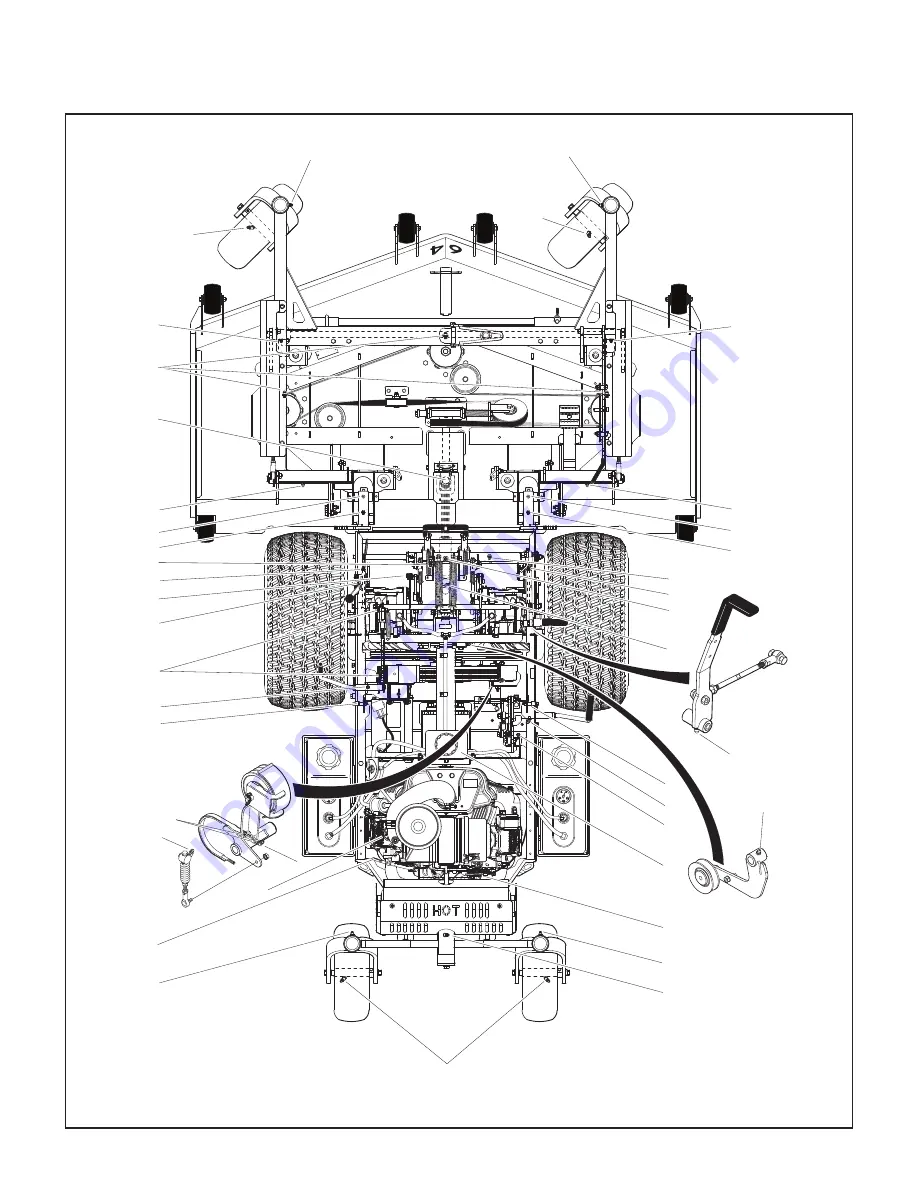
Lubrication
51
Chassis and Deck Lubrication Points
2
1
6
5
4
3
7
17 & 28
8
2613
45
30
29
27
10
9
11
17
19
18
16
15
21
14
13
20
22
24
23
25
12
Page 1: ...anual Safety Assembly Operating and Maintenance Instructions Please Read and Save These Instructions For Safety Read All Safety and Operation Instructions Prior to Operating Machine Beginning S N 174903 P N 2000 39 ...
Page 2: ...rator or others If anything in this manual is confusing or hard to understand please contact your local authorized dealer or call our service department at 970 221 5614 for clarification before operating or servicing this mower This manual covers Model H37i with the Briggs Stratton Vanguard 37 HP Electronic Fuel Injection EFI gasoline engine All shields and guards must be in place for the proper a...
Page 3: ...ch 27 Engine Throttle 28 Body Latch 28 Forward Speed Control FSC 28 Steering Levers 28 Blade Clutch PTO 28 Parking Brake 29 Oil Pressure Warning Light Horn 30 Engine Service Light 30 Over Temperature Warning Light Horn 30 Transaxle Lockout Arms 31 Circuit Breaker 31 Hourmeter 31 Roll Over Protection System ROPS Optional 32 Suspension Seat 33 Starting the Engine 36 Adjusting Ground Speed and Steeri...
Page 4: ...es and Clamps 62 Engine Starter 62 Transmission Control Setting 62 Neutral Park 62 Straight Ground Tracking 62 Blade Brake Action 62 PTO U Joints 62 Safety Switch System 63 Forward Speed Control Friction Lock 63 Replacing Repairing 64 Drive Belts 64 Engine PTO Belt 65 Ground Drive Belt 66 Deck Drive Belt 67 Fuel Filter 68 Mower Blades 68 Adjustments 70 Transmission Control 70 Steering Lever Positi...
Page 5: ...en the operator is seated facing forward in the tractor seat POWER TAKE OFF PTO transmits engine power to run the cutter blades REAR DISCHARGE RD discharges mowed material from the back of the mower deck RIGHT HAND RH refers to the right hand side of the tractor when the operator is seated facing forward in the tractor seat ROLL OVER PROTECTION SYSTEM ROPS offers enhanced operator protection in th...
Page 6: ... the limited warranty period it is important to find a local authorized servicing agent of the com ponent manufacturer Any unauthor ized work done on these components during the warranty period may void the warranty If you have any dif fi culty finding an authorized outlet or obtaining warranty service please contact our Service Depart ment for assistance Walker Manufacturing Company 5925 E Harmon...
Page 7: ...aded Gasoline 87 Octane Minimum 10 Ethanol Maximum Air Cleaner Engine Mounted Briggs Stratton Briggs Stratton P N 841497 Primary P N 821136 Safety Filter ELECTRICAL SYSTEM Battery 12 Volt 350 CCA Interstate SP 40 Charging System Flywheel Alternator Charging Output 50 Amp DC Regulated System Polarity Negative Ground Ignition Electronic Capacitive Discharge Starter 12 Volt Electric Ring Gear Type So...
Page 8: ...s Blade Drive Clutch and Brake Manual Belt Tightener Clutch and Band Brake Stops Blades within Five 5 Seconds of Disengagement TIRE SIZE Deck Caster Wheel 13 x 4 50 6 Pneumatic 6 Ply Drive 22 x 10 50 12 4 Ply Low Profile Tailwheel 13 x 4 50 6 Pneumatic 6 Ply TIRE PRESSURE PSI KPA Deck Caster Wheel 20 137 Drive 15 103 Tailwheel 20 137 DRIVE BELTS Engine PTO Walker P N 2230 Set of 3 Ground Drive Wal...
Page 9: ... Discharge Belt Driven Rear Discharge Belt Driven Side Discharge Cutting Width in cm 52 132 64 163 61 155 Cutting Height in cm 1 5 to 5 3 8 to 12 7 Height Adjustment in cm 1 4 1 Increments 15 Positions Blade Length in cm 18 4 47 22 2 56 20 5 52 Number of Blades 3 Direction of Rotation Viewed from top of deck Clockwise Deck Suspension Torsion Flex Frame with Caster Wheels and Counterweight Springs ...
Page 10: ...iew Body Tilt Up Latch Deck Height Lift Chain Deck Tilt Up Bar Deck Support Arm Not Visible Adjustable Footrests Forward Speed Control FSC Friction Adjustment Deck Lift Foot Pedal Raises Deck Cutting Height Release Lever Cutting Height Adjustment Deck Support Arm Tilt Up Latch Deck Tilt Up Socket Tilt Up Hook Deck Caster Wheels Counterweight Springs and Protective Covers ...
Page 11: ... View Adjustable Footrest Left Hand Drive Wheel Tail Wheel Fuel Pickup Line Fuel Tank and Cap Cylinder Head Cooling Fins Muffler Not Visible Fuel Gauge Oil Fill Dipstick Engine Air Cleaner Spread Axle Tail Wheel Tailpipe Muffler Heat Shield Body Lift Handle ...
Page 12: ...ol Rod Air Cleaner Cover Battery Fuel Gauge Roll Over Valve Air Cleaner Oxygen Sensor Oil Filter Not Visible Electronic Control Unit ECU Under Cover Oil Fill Not Visible Parking Brake Safety Switch Dipstick Fuel Tank Cap Fuel Tank Fuel Tank Selector Valve EVAP Line Fuel Filter Fuel Pickup Line Fuel Pump Low Pressure RH Transaxle Clutch Linkage RH Transaxle Lockout Arm Parking Brake Linkage Parking...
Page 13: ...ed by Walker Manufacturing must take full responsibility for safety The Walker Rider Lawnmower has been designed with many safety features to protect the operator from personal harm or injury However it is neces sary for the operator to use safe operating proce dures at all times Failure to follow safety instructions contained in this manual may result in personal injury or damage to equip ment or...
Page 14: ...AL PARK 2 PTO Clutch ENGAGED or 3 Parking Brake DISENGAGED NOTE There is a 1 2 second time delay function on the seat switch to avoid engine power interruption when driving over bumps 10 Handle gasoline with care Gasoline is highly flammable and its vapors are explosive a Use an approved fuel container b Never add fuel to a running engine or hot engine allow hot engine to cool several minutes c Ke...
Page 15: ...eewheel down the slope To maintain control immediately 1 Release the steering levers and simultane ously 2 Move the FSC to the NEUTRAL PARK position When the machine is stopped or moving slowly engage the parking brake NOTE The emergency stop procedure is exactly the same procedure as used to nor mally stop and park this machine 6 Disengage the blade clutch put the FSC in the NEUTRAL PARK position...
Page 16: ... tilt up position b Never tilt body forward with deck in tilt up position 18 In case of a clogged or plugged mower deck a Disengage the blade clutch PTO engage the parking brake and turn the engine off before leaving the seat b LOOK to make sure blade drive shaft move ment has stopped before trying to unclog the system c Disconnect the spark plug wires d Never place hands under the deck use a stic...
Page 17: ... attempt to disconnect any safety devic es or defeat the purpose of these safety de vices 9 Do not change the engine governor settings or overspeed the engine The governor has been factory set for maximum safe engine operating speed 10 Use genuine factory replacement parts Sub stitute parts may result in product malfunc tion and possible injury to the operator and or others 11 Use care when chargi...
Page 18: ... running engine can be deadly Do not operate indoors or in other enclosed areas Grease PTO shaft joints every 8 hours Location PTO Guard on Deck Part Number 8746 2 Location Each End of Mower Deck Part Number 8600 28 1 Warning thrown object hazard Keep bystanders away from the machine when operating Clear lawn of debris before operating Keep any discharge deflector in place and in the lowest positi...
Page 19: ...secure deck with straps and engage parking brake before transporting or trailering with deck tilted up Location Deck Height Adjuster Part Number 2748 2 Move pin to desired height of cut Location Flex Coupler Guard in Front of Engine Part Number 8600 2 Warning entanglement and cutting dismemberment hazards Keep away from rotating shafts belts and other components 8600 2 Location Deck Housing Under ...
Page 20: ...to stop 3 Body Tilt Latch Raise lever to release Lift at back of body to raise 4 Warning do not engage PTO clutch with PTO shaft disconnected 5 PTO Clutch Lever Move lever forward to engage PTO clutch back to disengage 1 Warning roll over crushing hazard Do not operate the machine on steep slopes or near drop offs Avoid quick and or sharp turns when operating on slopes 2 During normal operation al...
Page 21: ...fore operating the machine 3 Warning wear eye and ear protection when operating the machine 4 Warning read Operator s Manual before servicing or performing maintenance Engage parking brake Remove ignition key 5 Warning roll over hazard Do not operate on slopes greater than 15 degrees 6 Warning thrown object hazard Keep bystanders away from the machine when operating 7 Warning entanglement hazard K...
Page 22: ... checked or filled Battery Battery Location IMPORTANT Make sure battery is securely mounted in the frame A loose battery may cause damage to the case resulting in acid leakage and se vere damage to the machine A hazard may be cre ated by damage to critical working parts and safety systems CAUTION Important Battery Service Installation and Charging Tips For Electronic Fuel Injection Engines Do not ...
Page 23: ...battery is securely mounted in the frame A loose battery may cause damage to the case resulting in acid leakage and severe damage to the machine A hazard may be created by damage to critical working parts and safety systems Install the battery in the mower as shown in Bat tery Installation photo Connect the positive first and then the negative cable to the proper battery terminal red cable and boo...
Page 24: ...ge Shield Installation PTO Shaft Guard Installation Position the shaft guard as shown and mount with two 2 1 4 20 x 1 2 in bolts Attach Guard Carrier Frame Tube Socket PTO Shaft Guard Installation Tilt Up Roller Wheel Installation Mount the two 2 tilt up roller wheels on the brack ets on the rear skirt of the deck housing using the axle spacer tube 3 8 16 x 3 1 4 in bolt and 3 8 16 Whiz locknut Ti...
Page 25: ... is not required for installation Coupler Installation Tool Retract Spring Loaded Quick Disconnect Ring PTO Coupler Tube PTO Coupler Installation Tool 4 Unhook lower edge of rubber debris guard and raise for access to the tractor PTO shaft Re fer to Mower Deck Installation photo for location of debris guard Align Arrows Coupler Installation Tool Tractor PTO Shaft PTO Shaft Connection Shown with De...
Page 26: ...04 kg this adjustment is preset at the factory Counterweight Springs Clip Onto Body With Body Tilted Up Lynch Pins Lock Deck on Support Arms Not Visible Deck Counterweight Spring Installation Deck Leveling The mower deck and support frame are jig welded and the deck support linkage is factory adjusted Within normal tolerances very little if any adjust ment should be required to level the deck Tire...
Page 27: ... or right front support chain clevises to level the deck 4 Measure the front to rear level of the deck using a straight edge as shown in the Deck Leveling illustration The rear measurement should be 1 4 in 6 mm to 3 8 in 10 mm higher than the front measurement If neces sary adjust the right side height adjustment rod by lengthening it to lower the back of the deck or shortening it to raise the bac...
Page 28: ...se a clean fuel storage container and funnel IMPORTANT DO NOT mix oil with gaso line Always use fresh automotive grade unleaded gas oline DO NOT use gasoline containing greater than 10 ethanol DO NOT use additives such as carburetor clean ers deicers or moisture removing agents DO NOT use gasoline blended with methyl alcohol F CHECK ENGINE CRANKCASE OIL LEVEL Check the engine crankcase oil level b...
Page 29: ...Refer to Adjusting Cutting Height on page 40 F CHECK AND CLEAN GRASS BUILDUP UNDERNEATH MOWER DECK Refer to cleaning Grass Buildup in Mower Deck Housing on page 56 for deck tilt up and deck cleaning information DANGER Never operate cutter blades with deck in raised position because it is hazardous The tilt up deck is secured in the raised posi tion using the following procedure 1 Remove the tilt b...
Page 30: ...sition Tilt Bar Tilt Up Hook and Latch Connected Tilt Up Hook Tilt Up Latch Hitch Pin Deck Secured in TILT UP Position F CHECK MOWER BLADE CONDITION SHARPNESS AND SECURITY OF MOUNT ING The blade mounting nuts on gear driven decks should be torqued to 60 lb ft 81 N m and the blade mounting bolts on belt driven decks torqued to 70 lb ft 95 N m If blade sharpen ing is required refer to Sharpen Mower ...
Page 31: ...s to after starting and S is the START position When starting the engine turn the key clockwise to the S position Do not hold the key in the S position longer than 10 seconds If the engine does not start return the key to the O position for at least 60 seconds before making a restart attempt Prolonged crank ing can damage the starter motor and shorten battery life Release the key when the engine s...
Page 32: ... back on the steer ing levers overrides the FSC setting and slows or stops forward travel Releasing the steering levers allows the tractor to resume forward travel at the speed set by the FSC lever To stop and park the machine the FSC lever is moved backward to the NEUTRAL PARK position Steering Levers Each drive wheel is controlled by its own indepen dent steering lever for both steering function...
Page 33: ...a positive mechanical lock similar to the PARK posi tion on an automotive automatic trans mission If the tractor is moving when the brake is engaged it will result in sudden stoppage and possible internal damage to the transaxle NOTE If pressure on the parking brake e g parked on a hill makes it impossible to release the parking brake with the parking brake lever move the mower gently forward or b...
Page 34: ...gine performance When this light illumi nates during operation contact an authorized Briggs Stratton Service dealer to diagnose the fault IMPORTANT Continued operation of the engine with an illuminated engine service light will result in sub standard performance and MAY cause engine damage if not corrected as soon as possible Over Temperature Warning Light Horn The over temperature warning light a...
Page 35: ...rting system and the ignition system Hourmeter The hourmeter which is located on the right front of the body displays operating time accumulated while the ignition switch is in the ON RUN posi tion The hourmeter provides maintenance reminders after certain hours of operation The hourmeter screen will start flashing the reminder one hour prior to the recommended interval and will continue until one...
Page 36: ...ll bar is not in the fully upright and locked position o Never lower the ROPS roll bar when operating in areas where there are slopes drop offs or other roll over hazards o Be aware there is no roll over protection when the roll bar is lowered o Raise and lock the ROPS roll bar as soon as overhead clearance permits Check for overhead clearance e g branches doorways electrical wires before driving ...
Page 37: ...rried out If you fail to do so your health may be affected and the risk of accident increased CAUTION Before the tractor is used the safety switch must be checked for proper function The operation of the switch is checked by hav ing the operator lift off the seat with the tractor moving forward and or the blades engaged this action should cause the ma chine to stop If a malfunction is detected the...
Page 38: ... of the cover and loosen the hexagon nut size 13 mm situated behind it Set the armrests in the desired position 5 steps and tighten the hexagon nut Replace the cap onto the nut Refer to Figure 4 For Lumbar Support adjustment turning the knob upwards sets the curve in the upper part of the back upholstery Turning the knob downwards sets the curve in the lower part of the upholstery Refer to Figure ...
Page 39: ...k Position of the Steering Levers RIGHT WHEEL STEERING LEVER LEFT WHEEL STEERING LEVER Forward Position No Control Change Neutral Park Position Reverse Drive Wheel Motion Position Idle Position Fast Throttle Position Engaged Position Disengaged Position Disengaged Position Engaged Position Full Forward Ground Speed Position Intermediate Ground Speed Position Neutral Park Position FORWARD SPEED CON...
Page 40: ... to start the engine Release the key to ON RUN posi tion as soon as the engine starts IMPORTANT DO NOT crank the engine con tinuously for more than 10 seconds at a time If the engine does not start turn the key to the OFF position and allow a 60 second cool down period between starting attempts Failure to fol low these guidelines can damage the starter motor and shorten battery life Contact your W...
Page 41: ...MMENDATIONS Learn operation of the mower in an open area away from buildings fenc es and ob structions Learn opera tion on flat ground BEFORE operat ing on slopes Start maneuvering the mower with SLOW engine speed and SLOW For ward Speed Control setting until fa miliar with all operat ing characteris tics Remember it is not necessary to hold the steering levers forward a unique Walker feature alwa...
Page 42: ... NEUTRAL PARK position NOTE If the tractor creeps forward or back ward with the FSC lever in the NEUTRAL PARK position the transmission control needs to be adjusted For details refer to Adjust ments for Transmission Control Step 3 Neu tral Function Adjustment on page 71 WARNING In case the transmission drive belt breaks during operation and if the machine is on a slope the machine will freewheel d...
Page 43: ...throttle position 3 Disengage the blade clutch IMPORTANT DO NOT disengage the blade clutch with high engine speed above 1 2 throttle since the brake action on the blade drive will cause premature wear of the brake band WARNING A brake stops the cutter blades from free wheeling within five 5 seconds after dis engaging the clutch If the brake system malfunctions and the blades do not stop within fiv...
Page 44: ...el Tank Selector Valve ADJUSTABLE FOOT RESTS Some carrier frames are outfitted with adjustable foot rests To adjust rotate the footrests upward and slide to the desired position Rotate the foot rest down and insert the edge of the footrest into the nearest notch to lock in position Adjustable Footrest ADJUSTING CUTTING HEIGHT WARNING Never adjust cutting height while the mow er is moving Before ad...
Page 45: ... Towing can produce excessive internal pressure and damage the transaxle s To move the mower with the engine NOT running dead battery maintenance etc the transaxles need to be unlocked released 1 Raise the body 2 Pull up on each transaxle lockout arm and move back to engage the step that holds the arm in the UP unlocked position 3 The mower will freewheel with the arms in the LOCKOUT position The ...
Page 46: ... highest setting 5 in 127 mm for the first pass and then make a second pass cutting to the desired height Use a slow setting on the FSC for trimming operations Make sure the mower is leveled properly for a smooth cut Refer to Deck Leveling on page 22 Use an alternating stripe mowing pattern for best appearance and vary the direction of the stripe each time the grass is mowed to avoid wear patterns...
Page 47: ...d maneuver Avoid sharp turns or sudden changes in direc tion The maximum recommended slope operating angle is 15 degrees or 27 grade 60 in 16 in 15 Maximum Recommended Slope Do Not Operate on Steep Slopes Maximum Recommended Slope DANGER Do not mow or drive the tractor within 5 feet 1 5 meters of an embankment or retaining wall with drop off No Driving Zone 5 FT MINIMUM ...
Page 48: ...actor with the deck in the tilt up position since both the roller wheels on the back of the deck may be damaged by moving the tractor The tilt up configuration should only be used when the tractor is parked The tractor body should never be tilted forward with the deck in the tilt up position This can cause the deck to unhook from the tractor and fall with considerable force poten tially causing de...
Page 49: ...Engine Oil Filter x 48 Check Regap Spark Plugs x 61 Replace Fuel Filter x 68 Change Transaxle Oil and Filter ΔΔ x 52 Check Fuel Lines and Clamps x 62 Replace Air Filter Element Safety Filter Dust Ejection Valve x 54 Service Battery x 59 Service Solenoid Shift Starter x 62 Check PTO U Joints for Wear Looseness x 62 Check Transmission Control Settings x 62 Clean Engine Cooling Fins Remove Shroud x 5...
Page 50: ...cylinder head and feeling the cooling airflow DANGER Make sure to keep hands clear of exhaust pipe muffler and moving parts when checking airflow Operate the engine at full speed when mowing This allows the engine to produce full horsepower and move more cooling air through the engine cool ing fins Air Cleaner System Use only Briggs Stratton air cleaner elements Aftermarket elements may not seal i...
Page 51: ...pped Also make sure the engine is cool and oil has had time to drain into the sump allow at least five 5 minutes after stopping the engine IMPORTANT NEVER check or add oil with the engine running 2 Before removing the dipstick clean the area around the dipstick to keep any dirt or debris out of the engine 3 Remove the dipstick wipe off with a clean rag then reinsert the dipstick into the tube and ...
Page 52: ... 842921 After market oil filters may not seal properly and or may not have the correct pressure relief valve for proper lubrication 7 Install the new oil filter on the engine Turn the filter clockwise until the rubber gasket con tacts the sealing surface then tighten an additional 1 2 to 3 4 turn 8 Reinstall the oil drain plug and tighten until snug Do not overtighten 9 Fill the crankcase with new...
Page 53: ...om the bottom near the Cold Level line Hot Level Cold Level Hose to Transaxles Reservoir Cap Expansion Reservoir Location Grease Fitting and Oil Point Lubrication Lubricate the grease fittings and oil points after every 25 hours of operation Lubricate more often when operating in dusty or dirty condi tions Use SAE general purpose lithium or molyb denum base grease for grease fittings and light mac...
Page 54: ...rvoir Oil 20W 50 1 17 Throttle Control Cable Ends Oil 2 Ident Lubrication No No Location Type Places 18 Tail Wheel Caster Fork Pivot Grease 2 19 RearAxle Pivot Grease 1 20 Rear Wheel Bearing Grease 2 21 Engine Dipstick Oil 1 22 Engine Oil Fill Oil 1 23 PTO Belt Tightener Pivot Grease 1 24 ClutchActuator Push Rod Grease 1 25 Brake Band Pivot Pins Clevis Oil 2 26 Parking Brake Lever Pivot Grease 1 2...
Page 55: ...H37i Maintenance Instructions Lubrication 51 Chassis and Deck Lubrication Points 2 1 1 2 6 5 4 3 7 17 28 8 26 13 3 4 5 6 30 29 27 27 10 9 8 7 11 17 19 18 16 15 21 14 13 18 20 22 24 23 25 12 ...
Page 56: ... transaxles with 20W 50 API Service Class SL or higher oil through the opening where the elbows were Fill up to the open ing 6 Before reinstalling the elbows screw the lock ing nut on the elbows down until they are snug the o ring on the elbow will be to the bottom of the o ring groove Elbow Screw Locking Nut Down Reinstall Transaxle Elbows 7 Reinstall the elbows When the elbow begins to be snug p...
Page 57: ... baffling and a dust ejection valve provide dust separation and automatic precleaning action Daily or fre quent servicing of the air cleaner is not required IMPORTANT Use only Briggs Stratton air filter elements for replacement Briggs Stratton P N 841497 Primary Filter and P N 821136 Safety Filter Aftermarket filters may not seal properly or filter efficiently Canister Primary Filter Element Air C...
Page 58: ...Check the element very carefully for pin holes or other damage that will allow dirt to leak through the paper media Replace filter element if dirty or damaged 5 Check the condition and resilience of the radial sealing surface inside of the open end of the primary filter element Replace the filter if any cracks tears or other damage to the sealing surface are noted 6 Without removing visually inspe...
Page 59: ...ry to check and clean the screen several times each day to prevent engine over heating Also visually check inside cylinder head shroud and between cylinder head fins for material packed in this area which would prevent cooling airflow remove shroud and clean as required CAUTION Operating the engine with a blocked air in take screen dirty or plugged cooling fins and or cooling shrouds removed will ...
Page 60: ... Cooling Fins Viewed from Rear of Engine IMPORTANT Yearly it is good maintenance prac tice to remove the engine cooling shroud and clean the cylinder head cooling fins thoroughly to prevent overheating and extend engine life Make sure cooling shroud is reinstalled properly This proce dure will require removing the engine from the chassis Clean these areas of dirt and debris Clean Cooling Fins and ...
Page 61: ... Hook and Latch Connected Tilt Up Hook Tilt Up Latch Hitch Pin Deck Secured in TILT UP Position DANGER Do not operate the mower with deck in tilt up position Do not move the tractor with the deck in the tilt up position 6 Clean grass buildup underneath the deck using a pressure washer and scraper if re quired NOTE If the buildup is severe it may be easier to clean the deck by removing the deck ass...
Page 62: ... housing use compressed air and or a pressure washer Pay close attention to any oily dirt buildup on the transaxle housings This may be the result of an oil leak If an oil leak is noticed contact your local Walker dealer Cooling Fins Transaxle Housing and Cooling Fins IMPORTANT In case an oil leak develops on the input shaft the cooling fan blowing dusty air and oil on the transaxle will quickly c...
Page 63: ...cause damage to the case resulting in acid leakage and severe damage to the machine A hazard may be created by damage to critical working parts and safety systems CAUTION Important Battery Service Installation and Charging Tips for Electronic Fuel Injection Engines Do not allow the battery cables to touch opposing terminals When connecting battery cables attach the positive cable to positive batte...
Page 64: ...rp ness condition of the cutting edge and bal ance every 10 hours of operation or more often when mowing abrasive type grass or operating on sandy soils Replace blades if worn bent cracked or otherwise damaged refer to Mower Blades on page 68 Use the following proce dure to check and sharpen blades NOTE Keep blades sharp cutting with dull blades not only yields a poor mowing job but slows the cutt...
Page 65: ... Wall Mounted Balancer 7 Mount the blade with wing tips pointing up into the housing For gear driven decks reinstall the blade washer lock washer and nut Tighten the nut to 60 lb ft 81 N m For belt driven decks reinstall the spacer if ap plicable blade washer and bolt Tighten the bolt to 70 lb ft 95 N m Drive Belts Raise the body and inspect the condition of the four 4 drive belts after every 25 h...
Page 66: ...tment on page 71 Straight Ground Tracking Check for straight ground track by driving on a smooth level surface with hands off the steering levers Set the FSC at different speeds and observe if the mower moves in a straight line use a cement joint or other line on the ground for refer ence If the machine is drifting to the right or left refer to Adjustments for Transmission Control Step 5 Straight ...
Page 67: ...th the Forward Speed Control FSC and or PTO engaged or the parking brake disengaged With an operator in the seat the Forward Speed Control FSC and PTO disengaged the parking brake engaged and Oil Pressure Warning Horn sounding but the starter will not engage Forward Speed Control Friction Lock The FSC friction lock is designed to hold the selected forward travel speed when the steering levers are ...
Page 68: ...LWAYS use genuine factory replacement parts Substitute parts CAN result in product malfunction and possible injury to the operator and or others Drive Belts There are five 5 individual drive belts on the machine Engine PTO Belt Matched Set of 3 Ground Drive Belt Mower Blade Drive The belts may be removed and replaced using the procedures described on the following pages Belt Locations Engine Hidde...
Page 69: ...and RH Belt Guard by removing two 2 wing nuts b Remove two 2 wire lock pins and open Lower LH Belt Guard and PTO Belt Guard c Roll the belt off the pulley s and remove the belt Engine PTO Belt Belt Guards Open Engine Hidden for Clarity PTO Guard Wire Lock Pin Wire Lock Pin Right Hand Guard Wing Nut Clutch Idler Pulley Upper LH Guard Wing Nut Lower LH Guard PTO Belt s Matched Set PTO Pulley Fixed I...
Page 70: ...ease the idler pulley 2 Reverse the procedure to install the ground drive belt Ground Drive Belt Assembly Disengaged Ground Drive Belt Assembly Engaged Raise Idler Pulley to Relax Belt LH Transaxle Ground Drive Belt RH Transaxle Drive Pulley Transmission Belt Tensioner Arm Deck Tilt Bar Belt Tightener Idler Pulley LH Transaxle Ground Drive Belt RH Transaxle Drive Pulley Transmission Belt Tensioner...
Page 71: ... will then slip off the LH spindle pulley and can be completely removed 2 Install the deck drive belt by reversing the removal procedure a Route the belt as shown on the belt routing decal located on the deck housing Leave the belt loose at the LH spindle and then install the belt by compressing the belt tensioner as noted above b After the belt is in place reset the belt tensioner stop bolt by tu...
Page 72: ...ed and that no fuel leaks are present Mower Blades Mower blades are removed and remounted as described in Sharpen Mower Blades on page 60 During the course of sharpening and inspecting mower blades if there are any of the following conditions of wear or dam age blades should be replaced for reasons of safe ty and performance of the machine An excessive amount of the flat section of the blade has b...
Page 73: ... blade to assure safety Reinstall the blades following procedure from Sharpen Mower Blades on page 60 If blades are re placed always use Walker original equip ment blades to ensure safety and optimum perfor mance The quality and performance of replace ment blades offered by other manufacturers cannot be guar anteed they could be dangerous CAUTION ALWAYS use genuine factory replacement parts Substi...
Page 74: ...to one an other If they are not equal adjust accord ingly The handles may or may not be even at this point NOTE The LH steering lever is non adjust able This procedure will require adjustment of the RH lever to make it even with the LH lever Levers should sit parallel to each other Lever Alignment 2 Adjust the position of the RH lever by turning the stop bolt in the Speed Control Actuator in or ou...
Page 75: ...gth of Rod to Position FSC Lever FSC Lever Position Adjustment 2 Securely block the tractor up so the drive tires are off the ground 3 Adjust the tracking adjustment nuts at the front of both control rods so that 2 or 3 threads are visible then loosen the jam nuts on the ball joints at the back of the control rods Control Arm Tracking Adjustment Nuts Control Rods Transmission Control Rod and Arm L...
Page 76: ...ne set throttle at full speed and with the FSC in the NEUTRAL PARK position check for movement of either drive wheel if either wheel moves backward or for ward refer to Step 3 Neutral Function Adjustment on page 71 and readjust 2 Check for straight ground tracking on a level surface with hands off the steering levers Set the FSC at several different speeds and observe if the machine moves in a str...
Page 77: ...f the NEU TRAL PARK position If this distance is great er than 1 8 in 3 mm the FSC Neutral Switch needs to be adjusted downward for quicker activation Step 7 Forward Speed Control Friction Adjustment FSC Full Forward Position Pull Steering Levers Back to Check Friction Lock FSC Friction Adjustment Test Checking Friction Lock 1 Place the FSC lever in the full FORWARD position and pull both steering...
Page 78: ... in the PTO Clutch Engaged illustration If the clutch actuator link or clutch spring assembly have been disassembled first reset them to their factory preset lengths as shown in the PTO Clutch Disengaged illustration and then proceed with adjustment as follows Adjust the length of the clutch actuator link to achieve a clutch spring assembly bolt head clear ance of 1 4 in to 5 16 in 6 mm to 8 mm wi...
Page 79: ...nds after disengag ing the clutch Use the following procedures to check and adjust clutch disengagement and brake action Step 1 Idler Pulley Maximum Travel Adjust ment Loosen the brake band adjustment nut allowing clutch pivot stop arm and stop bolt to make contact refer to Blade Brake Band Adjustment illustra tion on page 76 1 To check the pulley travel first engage the clutch then measure the di...
Page 80: ...d it will be neces sary to adjust the blade brake band nut to maintain these dimensions CLUTCH DISENGAGED CLUTCH ENGAGED 5 8 in to 3 4 in 16 mm to 19 mm Clutch Idler Pulley Travel Adjustment Blade Brake Band Blade Brake Band Adjustment Nut Chassis Mount Ref Blade Brake Band Adjustment 2 After adjustments are complete check blade brake action as described in Blade Brake Action on page 62 If blades ...
Page 81: ...___________________________________________ ______________________________________________________________________________________________________________ ______________________________________________________________________________________________________________ ______________________________________________________________________________________________________________ _______________________...
Page 82: ...___________________________________________ ______________________________________________________________________________________________________________ ______________________________________________________________________________________________________________ ______________________________________________________________________________________________________________ _______________________...
Page 83: ... of the product alterations or failure to follow the instructions contained in the Operator s Manual for operation and maintenance B The customer shall pay any charges for making service calls and or for transporting the mower to and from the place where the inspection and or warranty work is performed 3 HOW TO OBTAIN SERVICE UNDER THIS WARRANTY Warranty service can be arranged by contacting the d...
Page 84: ...WALKERMFG CO 5925E HARMONYROAD FORTCOLLINS CO80528 970 221 5614 FORM NO 051822 PRINTED IN USA www walker com 2022 WALKER MFG CO ...