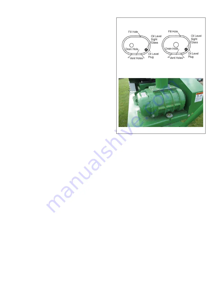
background image

45

FIG. 32 BLOWER

Schematic

Blower (Typical)

5.

Changing Oil:

a.

Place  a  collection  pan  or  pail  under  each  drain 
plug.

b.

Remove each drain plug.

c.

Flush  each  case  and  allow  several  minutes  to 
drain.

d. Dispose  of  the  oil  in  an  approved  manner.  Do 

not contaminate the worksite with used oil.

e.

Install and tighten the drain plugs.

f.

Remove fill and level plug.

g.

Add  Walinga

®

  Blower  oil  or  equivalent  to  each 

reservoir  until  the  oil  is  just  starting  to  come 
out  of  the  level  plug  hole  or  half  way  in  sight 
glass.

IMPORTANT

Condensation  forms  and  collects  inside 
the  reservoirs  during  machine  operation. 
Changing oil removes this water and
prevents  it  from  damaging  the  gears 
and bearings.

h. Install and tighten the level and fill plugs.

i.

Install and secure the belt/chain drive covers.

6.

Cleaning Breathers:

a.

Remove  breathers  and  blow  out  with  an  air 
hose.

b.

If  dirt  has  caked  up  in  the  breather,  soak  in 
good  solvent  and  then  blow  out.  It  may  be 
necessary to use a probe to loosen the dirt.

c.

Install and tighten the breather.

e.

Install and secure the belt drive covers.

f.

Clean  vents  in  end  plates  located  under  the 
blower on either side of the drain plug.

Summary of Contents for Agri-Vac 3510

Page 1: ...AGRI VAC 3510 TOUGH TO BEAT IN THE LONG RUN Model 3510 Gas and Electric OPERATOR S MANUAL and PARTS BOOK...

Page 2: ......

Page 3: ...Installed Check Tire Pressure Reflectors and Signs Clean Wheel Bolts Tight Review Operating and Safety Instructions Lubricate Machine Operating Manual Supplied Check Oil Level in Reservoirs Belts are...

Page 4: ......

Page 5: ...e of the warranty period then remaining provided that Walinga consents in writing to such transfer of warranty The Walinga Warranty is conditional upon proper storage installation use maintenance oper...

Page 6: ...any one or more of the following reasons The warranty claim information provided is insufficient The product evaluation does not substantiate the claim The unit has been operated above and beyond its...

Page 7: ...0 466 1197 jpk walinga com ORIGINAL PARTS SALES Ontario and Eastern Canada Scott Lodder ext 224 spl walinga com Parts Department Fax 519 824 0367 Manitoba and Western Canada Chad Yeo 204 745 2951 chad...

Page 8: ...ice or other information Serial number plates are located where indicated Please mark the numbers in the spaces provided for easy reference SERIAL NUMBER LOCATION Airlock Serial Number _______________...

Page 9: ...NOTES...

Page 10: ...y 8 2 14 Tire Safety 8 2 15 Battery Safety 8 2 16 Gas Motor Safety 9 2 17 Safety Around Bins Silos Tanks etc 10 2 18 Employee Sign Off Form 11 4BGFUZ 4JHO PDBUJPOT 13 4 Operation 17 4 1 To the New Ope...

Page 11: ...e operating or maintaining the Agri Vac read understand and practice ALL of the Safety Operation Maintenance and Trouble Shooting recommendations contained within this Operator s Manual This manual ap...

Page 12: ...ided 3 Big Reasons DANGER Indicates an imminently hazardous situation that if not avoided will result in death or serious injury This signal word is to be limited to the most ex treme situations typic...

Page 13: ...d anyone else who is going to operate maintain or work around the Agri Vac be familiar with the operating and maintenance procedures and related SAFETY information contained in this manual This manual...

Page 14: ...ildren and persons unfamiliar with its operation The opera tor should be a responsible properly trained and physically able person familiar with farm machin ery and trained in this equipment s operati...

Page 15: ...ent quickly in an emergency Read this manual and the one pro vided with your other equipment 6 Train all new personnel and review instructions frequently with existing workers Be certain only a proper...

Page 16: ...ATION 1 Never operate the Agri Vac and auxiliary equip ment until you have read and completely un derstand this manual the auxiliary equipment Operator s Manual and each of the Safety Messages found o...

Page 17: ...is an invitation to trouble Follow all operating maintenance and operating instruc tions in this manual 2 Follow good shop practices Keep service area clean and dry Be sure electrical outlets and too...

Page 18: ...rking condition 4 Disconnect grain and vacuum lines and plug be fore transporting 5 Do not drink and operate 2 13 REFUELING SAFETY 1 Handle fuel with care It is highly flammable 2 Allow engine to cool...

Page 19: ...engine starts 15 DO NOT strike flywheel with a hard object or metal tool as this may cause flywheel to shatter in opera tion Use proper tools to service engine 16 DO NOT operate engine without a muffl...

Page 20: ...working in such structures 4 The atmosphere within a bin silo tank or storage structure should be tested for the presence of combustible gases dusts vapors and toxic agents 5 Ventilation should be pr...

Page 21: ...low anyone else to operate this equipment until such information has been reviewed Annually review this information before the season start up Make these periodic reviews of SAFETY and OPERATION a sta...

Page 22: ...NOTES...

Page 23: ...urself with the various Safety Signs the type of warning and the area or particular function related to that area that requires your SAFETY AWARENESS Think SAFETY Work SAFELY REMEMBER If Safety Signs...

Page 24: ...arious Safety Signs the type of warning and the area or particular function related to that area that requires your SAFETY AWARENESS Think SAFETY Work SAFELY REMEMBER If Safety Signs have been damaged...

Page 25: ...arious Safety Signs the type of warning and the area or particular function related to that area that requires your SAFETY AWARENESS Think SAFETY Work SAFELY REMEMBER If Safety Signs have been damaged...

Page 26: ...the various Safety Signs the type of warning and the area or particular function related to that area that requires your SAFETY AWARENESS Think SAFETY Work SAFELY REMEMBER If Safety Signs have been da...

Page 27: ...and move it in a stream of pressurized air A high capacity air pump moves the air through the machine creating a vacuum on the intake side and pressure on the outlet side Be familiar with all operati...

Page 28: ...separated from the stream of air in the receiver tank FIG 1 MACHINE COMPONENTS On the discharge side of the blower the pressurized air flows through the airlock where it picks up a metered quantity of...

Page 29: ...ly 6 Close and secure all guards 4 3 MACHINE BREAK IN Although there are no operational restrictions on the Agri Vac when used for the first time it is recommended that the following mechanical items...

Page 30: ...t space to locate the machine and allows you to move around the unit to access the controls 3 Block the wheels to prevent movement 4 Remove the plugs from the receiver tank inlet and airlock outlet 5...

Page 31: ...position where the engine will con tinue to operate START Turn fully clockwise to the last spring loaded detent position to engage the starter solenoid and start the engine Release the key when the e...

Page 32: ...Vac can be wired into a large control room away from the machine or controlled by the control box supplied with the unit If part of a con trol system the customer must provide all the nec essary compo...

Page 33: ...NSTALLED OPERATING SAFETY Read and understand the Operator s Manual and all safety signs before operating maintain ing adjusting or repairing the Agri Vac Before servicing adjusting repairing or main...

Page 34: ...o fully warm engine before increasing to full RPM Refer to engine owner s manual for complete start up details 6 Stopping A Electric a Remove nozzle from grain and allow to empty b Depress red STOP bu...

Page 35: ...e past the window for the best performance 9 Maximum Capacity a Place the nozzle into the grain with the inlet below the surface of the grain but not below the airslide It is necessary that some air b...

Page 36: ...dealer or the factory for details 11 Entering Bins a Open the vents to provide ventilation and to allow air to replace grain being removed b Do not enter bin if the grain is crusted or has built up a...

Page 37: ...flow to prevent it from going through the blower b Reducer To change size from 3 inch diameter to 2 inch diameter or from 4 inch to 3 inch c Brush End Brush for cleaning up dust and loose grain d Whee...

Page 38: ...e ra dius elbow d Keep lines as short as possible to minimize friction losses e If long distance moving is required push the grain rather than pull f If long distance moving is required use solid meta...

Page 39: ...ng Do not drink and operate Walinga Agri Vacs are designed to be easily and conveniently moved from location to location When transporting follow this procedure 1 Be sure all bystanders are clear of t...

Page 40: ...nt rusting 6 All hoses should be stored inside or under a shelter 7 Move the machine to its storage position 8 Select an area that is dry level and free of debris 9 Motors should be stored in a clean...

Page 41: ...en carrying out any maintenance and repairs or making any adjustments 5 SERVICE AND MAINTENANCE 5 1 SERVICE 5 1 1 FLUIDS AND LUBRICANTS 1 Grease Use an SAE multi purpose high temperature grease with e...

Page 42: ...8 Hours or Daily 1 Use the sight glasses to check the oil level in the blower reservoirs 2 locations 2 Check engine fluid levels gas model only a Fuel b Oil level FIG 14 RESERVOIRS FIG 15 GAS ENGINE...

Page 43: ...or Weekly 1 Grease airlock drive jack shafts and bearings 2 Check drive belt and chain tension 3 Clean gas engine air filter FIG 16 JACK SHAFT BEARINGS FIG 17 BELT AND CHAIN TENSION Gas Electric FIG 1...

Page 44: ...in the blower oil reservoirs 2 loca tions and clean head plate vent holes 2 Change engine oil drain plug 3 Change engine oil filter 4 Change inline fuel filter FIG 19 BLOWER FIG 20 ENGINE Schematic Bl...

Page 45: ...35 FIG 22 STEERING WHEEL BUSHING 5 Grease steering wheel bushing...

Page 46: ...ANGE MAINTENANCE HOURS SERVICED BY 8 Hours or Daily CK Blower Oil Level 2 locations CK Engine fluid levels 2 locations 40 Hours or Weekly G Airlock Drive Jack Shafts G Airlock Drive Bearings CK Drive...

Page 47: ...iew the Operator s Manual for the engine 2 Place all controls in neutral stop engine remove ignition key and wait for all moving parts to stop before maintaining 3 Remove the cover over the air cleane...

Page 48: ...drain plug 5 Remove the drain plug and allow the oil to drain for 10 minutes 6 Install and tighten the drain plug 7 Dispose of the used oil in an approved container 8 Remove engine oil filter 9 Apply...

Page 49: ...ts dirty To change the filter follow this procedure 1 Place all controls in neutral stop engine remove ignition key and wait for all moving parts to stop before maintaining 2 Apply clamps to fuel line...

Page 50: ...standers especially small children 2 Stop the unit wait for all moving parts to stop be fore maintaining 3 Ensure that the unit power source is completely shut down and can not start up Lock out tag o...

Page 51: ...ligned c Measure the distance the pulley needs to move d Loosen belts e Remove bolts from the pulley which is to be moved f Install bolts into pulleys threaded holes and force pulley from bushing Use...

Page 52: ...low this procedure a Determine the type of pulley mis alignment b Loosen belts c Loosen power unit base anchor bolts d Loosen position bolt jam nuts e Use position bolts to move power unit base on eac...

Page 53: ...ause sprocket damage Follow this procedure when checking and adjusting chain tension 1 Clear the area of all bystanders especially small children 2 Stop the unit and wait for all moving parts to stop...

Page 54: ...the belt drive covers 4 Checking Oil Level a Remove the level plug in each reservoir or check the sight glass b Oil in the reservoir should just fill the threads of the level plug hole c Add oil if l...

Page 55: ...le or half way in sight glass IMPORTANT Condensation forms and collects inside the reservoirs during machine operation Changing oil removes this water and prevents it from damaging the gears and beari...

Page 56: ...en vacuum and pressure sides When checking or maintaining the airlock follow this procedure 1 Clear the area of bystanders especially small children 2 Checking Tip Clearance a Checking the airlock can...

Page 57: ...ps g Install tank top h Install belt chain cover 6 Tip Replacement a Ensure the unit power source can not start up b Lift the receiver tank off the airlock c Remove the tips from the rotor d Mount the...

Page 58: ...NOTES...

Page 59: ...k hose coupling gaskets Tighten receiver coupling to base Check seal on pre cleaner bottom door if so equipped Close and secure Check blower belt tension Improper setting of airslide Reset airslide De...

Page 60: ...uantity by closing airslide Blower bogging down Blower oil lacking Change oil contact dealer Belts slipping Tighten belts Power source slowing Check power source 6 2 AIRLOCK PROBLEM CAUSE SOLUTION Noi...

Page 61: ...to recom mended RPM Pressure too high Adjust operating conditions to reduce pressure rise to below 6 psi Impellers rubbing Consult your nearest dealer 6 4 V BELT DRIVE PROBLEM CAUSE SOLUTION Loss in d...

Page 62: ...NOTES...

Page 63: ...or 20 hp 7 5 11 15 kw 540 PTO 25 hp STARTER 12 volt ATL Not applicable RECEIVER 18 dia x 36 high 46 x 91cm 18 dia x 36 high 46 x 91cm 18 dia x 36 high 46 x 91cm INLET 4 100mm daffin coupling with plug...

Page 64: ...odically using bolt torque chart as a guide Replace hardware with the same strength bolt Diameter SAE 2 SAE 5 SAE 8 1 4 5 16 3 8 7 16 1 2 9 16 5 8 3 4 7 8 1 8 13 27 41 61 95 128 225 230 345 6 10 20 30...

Page 65: ...4PLY W PARTS 26 30 97030 5 A L 1210DT FXR V ROTOR FLEX TIP 27 38 04465 5 DP 4 PLUG WITH CHAIN 28 43 09877 5 BLOWER 510 CHR 3 25 29 51 91362 6 ELB 5x90D DBL BEND 5 5 CLR 14GA CS 30 56 01100 1 PIPE STL...

Page 66: ...57 NOTES...

Page 67: ...57 NOTES...

Page 68: ...gn Off Form 11 Equipment Safety Guidelines 4 Gas Motor Safety 9 General Safety 3 Installation Safety 6 Lock Out Tag Out Safety 6 Maintenance Safety 7 Operating Safety 7 Preparation 6 Refueling Safety...

Page 69: ......

Page 70: ...38 Glengarry Cres Fergus Ontario Canada N1M 2W7 Tel 519 787 8227 Fax 519 787 8210 DISTRIBUTION AND SERVICE CENTRES 5656 Highway 6N Guelph Ontario Canada N1H 6J2 Tel 888 925 4642 FAX 519 824 5651 1190...

Reviews: