17
Cleaning and Maintenance
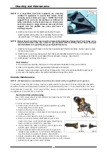
Fig 5
Burner Base
Trivets and Burners
a. Remove trivets from top of appliance, taking note that
trivets are manufactured with a lip on one edge, lip must
always be fitted to outer edge (front and back) of range.
(See Fig 10).
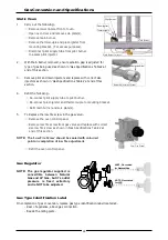
b. Remove burner cap and burner bowl (these are a loose
fit to manifold, see Fig 5) from top of gas manifold,
taking care not to damage thermocouple (and pilot tube
- PF Option) fitted through manifold splash guard.
(Refer to Fig 8 for 'F' Option and Fig 9 for 'PF' Option).
c. Trivets and burners should be cleaned with a mild
detergent and hot water solution using a soft bristled
brush. Dry thoroughly with a dry cloth.
Trivet Supports
a. Remove all trivet supports from top of appliance. Note
orientation of trivet support when removing. Trivet
support front end side rail profiles are different from rear
end side rail profiles.
(See Note shown at Item a, in ‘Re-
Fitting the Components to the Range’ on following page
and Fig 6).
b. Trivet supports should be cleaned with a mild detergent
and hot water solution using a soft bristled brush.
c. Dry trivet supports thoroughly with a dry cloth.
Stainless Steel Surfaces
a. With griddle plates and burners removed, clean interior
and exterior surfaces of range with hot water, a mild
detergent solution and a soft scrubbing brush. Note that
gas control knobs are a push fit onto gas control valve
spindles and can be removed to allow cleaning of front
control panel.
b. Baked on deposits or discolouration may require a good
quality stainless steel cleaner or stainless steel wool.
Always apply cleaner when appliance is cold and rub in
direction of grain.
c. It should not be necessary to remove splash guards
covering burner manifolds for cleaning purposes. These
can be cleaned in situ.
d. Dry all components thoroughly with a dry cloth and
polish with a soft dry cloth.
e. To remove any discolouration, use an approved stainless
steel cleaner or stainless steel wool. Always rub in
direction of grain.
f. Remove grease tray and clean with a mild anti bacterial
detergent and hot water solution using a soft bristled
brush.
g. Dry grease tray thoroughly with a dry cloth.
h. Dry all components thoroughly with a dry cloth and
polish with a soft dry cloth.
Re-Fitting the Components to the Range
a. Refit trivet supports to range, ensuring that these are
correctly fitted.
Burner Bowl
Locating Holes
Fig 7
Notice Difference
in Profiles
Fig 6
Fig 5
Burner Bowl
Burner Cap
Burner Base Locates onto
Cap Screw and over Flange
Fig 8
F - Option
Fig 9
Shown without Pilot
Burner Shield fitted.
Pilot Burner
Thermocouple
PF - Option

