background image

18 

Replacement Parts List 


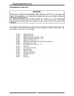
When ordering replacement parts, please quote the part number and the description as listed below.  If the 

part required is not listed below, request the part by description and quote model number and  
serial number which is shown on the rating plate. 


Replacement Parts List


IMPORTANT: 


Only genuine authorized replacement parts should be used for the servicing and  
repair of this appliance.  The instructions supplied with the parts should be followed 

when replacing components. 

For further information and servicing instructions, contact your nearest authorized  

service branch (contact details are as shown on the reverse of the front cover of this  

manual). 

233706 

Induction Glass 450. 

233705 

Induction Glass 900. 

234480 

Induction Generator Vario Quad - 2 Tray. 

234481 

Induction Generator Vario Quad - 4 Tray. 

234482 

Induction Coil Tray 2 Zone. 

234693 

Induction Control Rotary Switch Assembly (Includes LED’s). 

227398 

Knob Waldorf 6 mm, HI-4-3-2-1-LO. 

020774 

Microswitch. 

227850 

Leg 150 mm (Flush Stud). 

229674 

Rear Roller Assy. 

235137 

Induction Air Filter. 

235351 

Thumb Screw (for Filter). 

227856 

Magnetic Door Catch. 

235308 

LED Red. 

235307 

LED Green. 

235309 

Potentiometer with Switch. 

Summary of Contents for IN8200E

Page 1: ...1 I n s t a l l a t i o n a n d O p e r a t i o n M a n u a l Induction Cooktop IN8200E IN8400E Date Purchased Serial Number Dealer Service Provider 235034 2 INL8200E INL8400E For use in GB IE...

Page 2: ...337 963 Customer Service tel 1800 335 315 fax 1800 350 281 CANADA Serve Canada Web www servecanada com E Mail info servecanada com Sales tel 800 551 8795 Toll Free Service tel 800 263 1455 Toll Free N...

Page 3: ...tion Dimensions 6 Installation 7 Installation Requirements Unpacking Location Clearances Assembly Electrical Connection Commissioning Operation 10 Operation Guide Description of Controls Operating the...

Page 4: ...ENANCE CAN CAUSE PROPERTY DAMAGE INJURY OR DEATH READ THE INSTALLATION OPERATING AND MAINTENANCE INSTRUCTIONS THOROUGHLY BEFORE INSTALLING OR SERVICING THIS APPLIANCE WARNING GREAT CARE MUST BE TAKEN...

Page 5: ...if the appliance is turned On Beware that when using the induction unit personal items such as rings watches and similar ob jects could get hot when in close proximity to the cooking zone Do Not place...

Page 6: ...rd they offer easy operation the latest technology and maximum convenience for Boiling Roasting Keeping Food Warm Flamb ing Grilling The pan bottom is heated directly with a minimum of energy loss wit...

Page 7: ...quivalent synthetic elastomer sheathed cord as per AS NZS 3191 part 2 10 11 or IEC 60245 IEC 57 e g HO5 RN F Type The branch supply line shall be individually overload protected to the correct current...

Page 8: ...6 Dimensions Dimensions IN L 8200E IN L 8400E...

Page 9: ...ill void the warranty Components having adjustments protected e g paint sealed by manufacturer are only to be adjusted by an authorised service agent They are not to be adjusted by the installation pe...

Page 10: ...he Specifications section of the manual 3 Bring the supply cable up through the compression type gland provided on the rear of the main electrical switchgear panel 4 Connect the mains supply to L1 L2...

Page 11: ...lled induction pan minimum of 120 mm diameter on the cooking zone i The Green Indicator lamp must be On continuously j Adjust power to Maximum k After a few seconds the fan must turn On If an error oc...

Page 12: ...ob If the hob is turned On without a pan on the hob the lamp will commence flashing until a pan is placed on the selected hob Also used with the Fault Lamp to display Generator Faults refer to Error C...

Page 13: ...t the highest setting and change to a lower setting when the desired temperature is reached 1 Turn power On at the mains power supply 2 Place cooking pan onto the hob to be used ensuring that there is...

Page 14: ...ting at peak efficiency follow the procedures shown below After Each Use 1 Clean the Induction Cooktop hob area with a plastic or wooden scraper tool to remove any food debris 2 Wipe down with a damp...

Page 15: ...b Baked on deposits or discolouration may require a good quality stainless steel cleaner or stainless steel wool Always apply cleaner when the appliance is cold and rub in the direction of the grain...

Page 16: ...be found on the Technical Data Plate located on the appliance Fault Possible Cause Remedy Insufficient heating of the cooking zone Unsuitable pan material Use only approved pans Continuous heating of...

Page 17: ...eld has cooled down Temperature Sensor faulty Replace Temperature Sensor Power Board faulty Replace Generator E1 05 Control Unit failure Defective wiring or Control Unit Check wiring harness to unit o...

Page 18: ...ut1 out2 MICROSWITCH COIL COIL MAINS CONNECTION 400 415v 3P E POTENTIOMETER NEONS POTENTIOMETER NEONS INDUCTION GENERATOR W F PU W F PU B C W F PU W F PU COIL AND COIL TEMPERATURE SENSOR CONNECTION DE...

Page 19: ...oti Lamps CONTROL D gn rt COIL COIL POTENTIOMETER NEONS POTENTIOMETER NEONS POTENTIOMETER NEONS POTENTIOMETER NEONS INDUCTION GENERATOR Digital I O ln out1 out2 MICROSWITCH CONNECTION CONTROL PANEL W...

Page 20: ...mponents For further information and servicing instructions contact your nearest authorized service branch contact details are as shown on the reverse of the front cover of this manual 233706 Inductio...

Page 21: ......

Reviews: