27
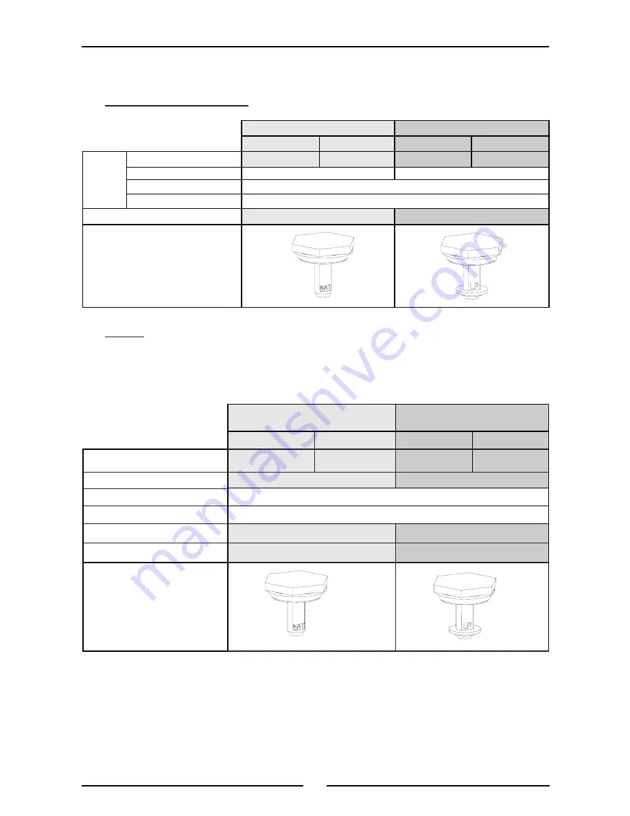
Gas Conversion and Specifications
Gas Specifications
- Australia / New Zealand Only
- UK Only
Appliance Classification
Category:
II
2H3P.
Flue Type:
A
1.
Note 1 The Gas Control Valve is fitted with a maximum flow bypass blanking screw, non
adjustable.
Note 2 The burner operating pressure is to be measured at the griddle gas control valve outlet test
point with one griddle burner operating at full setting. The operating pressure is ex-factory
set, through the appliance regulator and is not to be adjusted, apart from when carrying out
gas conversion, if required. (Refer to the ‘Gas Conversion’ section for details).
Natural Gas (G20)
Propane (G31)
GP8910GE/GEC
GP8121GE/GEC GP8910GE/GEC GP8121GE/GEC
Main Burner Injector
3.00mm
2.85mm
1.80mm
1.70mm
Pilot Burner Injector
0.41
Low Fire Adjustment
1 Full Turn Counter Clockwise from the 'Fully In' Position
High Fire Adjustment
Maximum Flow Screw. Fully In c.w. (Note 1)
Operating Pressure
8.2 mbar (Note 2)
26 mbar (Note 2)
Supply Pressure
20 mbar
37 mbar
Gas Regulator Cap Screw
0.25
Natural Gas
LP Gas (Propane)
GP8910GE/GEC GP8121GE/GEC GP8910GE/GEC GP8121GE/GEC
Griddle
Main Burner
3.00mm
2.85mm
1.80mm
1.70mm
Pilot Burner
0.41
0.25
Low Fire Adjustment
1 full turn counter clockwise from the Fully ‘IN’ position
High Fire Adjustment
Maximum Flow Screw. Fully ‘IN’ (Note 1)
Operating Pressure
0.90 kPa (Note 2)
2.6 kPa (Note 2)
Gas Regulator Cap Screw
Summary of Contents for GP8910GE
Page 8: ...6 Dimensions GP L 8910GE GEC GP L 8121GE GEC...
Page 21: ...19 GP8910GE and GP8121GE Wiring Schematics...
Page 22: ...20 Wiring Schematics Wiring Diagram GP8910GE GP8121GE...
Page 23: ...21 GP8910GEC and GP8121GEC Wiring Schematics...
Page 24: ...22 Wiring Schematics Wiring Diagram GP8910GEC GP8121GEC...
Page 32: ...30...


