Walchem WDT400 Series Instruction Manual Download Page 28

5.11 Datalog 

Menu 

This menu is available if the data logging option has been purchased. This is indicated in the model 
code by the letter U at the end of the model code. This menu allows you to save data from the controller 
to a USB flash drive. 

The controller has four logs, the Current Datalog, the Backup Datalog, the Event Log, and the Reset 
Log. All files are in a CSV format that may be opened in a spreadsheet such as Microsoft Excel. 

Current Datalog 


Contains the following data taken at 10 minute intervals for each tower:

 Conductivity

 Temperature 

 Water 

Meter 

Total 

When the current datalog is downloaded to a USB stick, it is erased and a new log file is started. 

If the current datalog is not downloaded before it reaches its maximum size (at least 60 days of 
data) the oldest data is overwritten by the newest data. 

Backup Datalog 


Contains the same data as the current log but it is never erased. When the backup log reaches its 
maximum size (at least 60 days of data), the oldest data is overwritten by the newest data. 

Event Log 


Contains columns for each relay and flow switch input, as well as the date and time. Each time 
any of these change state, the date and time is updated and it will show a 1 if the relay is on and 0 
if it is off, and a 1 if the flow switch indicates no flow, 0 if there is flow. Tens of thousands of 
events will be recorded before the oldest data is overwritten by the newest, the number varying 
with the controller’s configuration. 

Reset Log


Consists of time stamps of when power was lost, when it was returned, and the cause of the reset. 

Current or Backup 

Datalog 

Place a USB flash drive with at least 10 MB capacity into the USB port on the front panel of the 
controller. Press the Enter key to download the file from the controller to the disk. The file name for 
the Current Datalog will be Datalog<serial number><date><time>.csv using the date and time it was 
downloaded. The file name for the Backup Datalog will be Datalog<serial number><date><time> 
.csv using the date and time it was created. 

The controller will display the progress of the file download process. If the file was successfully 
copied to the USB disk the controller will display Transfer Success. 

Copy Event Log 

Place a USB flash drive with at least 10 MB capacity into the USB port on the front panel of the 
controller. Press the Enter key to download the file from the controller to the stick. The file name 
will be Eventlog<serial number><date><time>.csv. 

The controller will display the progress of the file download process. If the file was successfully 
copied to the USB disk the controller will display Transfer Success, otherwise Transfer Fail 1. 

Transfer Success 

Transfer Fail 1 

Copy Reset Log 

Place a USB flash drive with at least 10 MB capacity into the USB port on the front panel of the 
controller. Press the Enter key to download the file from the controller to the stick. The file name 
will be Resetlog<serial number><date><time>.csv. 

The controller will display the progress of the file download process. If the file was successfully 
copied to the USB disk the controller will display Transfer Success. 

Transfer Success 

Transfer Fail 1 

Datalog 
Current Datalog 

Datalog 
Copy Event Log 

Datalog Menu 

ENTER


EXIT


67° F 

Datalog 

2000 µS 

Datalog 
Transfer Success 

Next 

Prev 

Datalog 
Copy Reset Log 

Next 

Prev 

ENTER


EXIT


ENTER


EXIT


ENTER


EXIT


Datalog 
Transfer Success 

Datalog 
Transfer Success 

Possible Status Screens 

Transfer Success 

Transfer Fail 1 

Datalog 
Backup DataLog 

Next 

Prev 

ENTER


EXIT


Datalog 
Transfer Success 

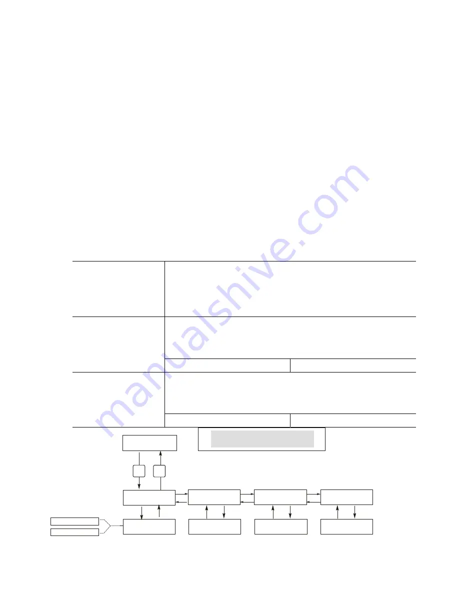
Figure 17 Datalog Menu 

25 

Summary of Contents for WDT400 Series

Page 1: ...A L C H E M IWAKI America Inc WDT400 Series Dual Cooling Tower Conductivity Controller Instruction Manual Five Boynton Road Hopping Brook Park Holliston MA 01746 USA TEL 508 429 1110 FAX 508 429 7433...

Page 2: ...chanical parts and electrodes from date of delivery from the factory or authorized distributor under normal use and service and otherwise when such equipment is used in accordance with instructions fu...

Page 3: ...tup 11 4 6 Shut Down 11 5 0 OPERATION 12 5 1 Main Menu 12 5 2 Conductivity A or B Menu 14 5 3 Temperature A or B Menu 16 5 4 Bleed A or B Menu 17 5 5 Feed A or B Menu 18 5 6 WM1 and WM2 Menu 20 5 7 Al...

Page 4: ...o the conductivity reading are available for all models Any set point may be viewed without interrupting control Each set point change will take effect as soon as it is entered An access code is avail...

Page 5: ...one group total current for this group must not exceed 6A 4 20 mA 0 1 or 2 optional Fully isolated 600 Ohm max resistive load Resolution 001 of span Accuracy 1 of reading Agency Approvals Safety UL 61...

Page 6: ...ed Cycle Time Mode C 10 minutes 59 min 59 sec Time per Contact Mode D 1 second 59 min 59 sec Contacts by Mode D 1 contact 100 contacts Time Limit Mode D E 1 minute 99 min 59 sec Time Vol Mode E 1 seco...

Page 7: ...uires the following clearances Top 2 50 mm Left 8 203 mm Right 4 102 mm Bottom 7 178 mm 3 3 Installation Once the WDT series controller is mounted the metering pumps may be located at any distance fro...

Page 8: ...WER BLEED METERING VALVE PUMP HEAT EXCHANGER System A Cooling Tower Controller www walchem com PREV NEXT ENTER EX T COOLING TOWER BLEED VALVE METERING PUMP HEAT EXCHANGER System B Figure 1 Typical Ins...

Page 9: ...e between 22 26 AWG Shield should be terminated at the controller ground stud see figures 3 and 4 CAUTION 1 There are live circuits inside the controller even when the power switch on the front panel...

Page 10: ...ptional CONDUCTIVITY ELECTRODE B CONDUCTIVITY ELECTRODE A FLOW SWITCH A OPTIONAL POWER BLEED A ALARM 4 20 mA 1 optional FLOW METER B OPTIONAL FLOW SWITCH B OPTIONAL FLOW METER A OPTIONAL FEED A Figure...

Page 11: ...R 1 IN IN IN IN IN IN IN COND RED BLK 5V T T SYSTEM B L1 L2 N COND T T 5V RED BLK WHT 120V BLU 240V SYSTEM A SHIELD SYSTEM B SYSTEM A COND T T 5V RED BLK FLOW SW 1 FLOW SW 2 FLOW MTR 2 FLOW MTR 1 IN I...

Page 12: ...120V BLU 240V WHT 120V BLU 240V WHT 120V BLU 240V WHT 120V BLU 240V BLK 120V BRN 240V BLK 120V BRN 240V IF MOTORIZED BALL VALVE BLK 120V BRN 240V BLK 120V BRN 240V WHT 120V BLU 240V BLK 120V BRN 240V...

Page 13: ...pper left side tower B on the upper right side and current operating conditions The operating conditions that are displayed on the bottom line of this display are Temp Err A Temp Err B Cond Err A Cond...

Page 14: ...see Section 5 11 for operation With the access code enabled any user can view parameter settings but not change them Note that this provides protection only against casual tampering Use a lock on the...

Page 15: ...our WDT controller determines which menus are available as you scroll through the settings Certain menus are only available if you select certain options Main Menu Top Level Tower A Tower B Access Cod...

Page 16: ...Holding A B Stops Conductivity Control These conditions trip the diagnostic alarm relay Operation Press Enter key to enter menu Press Exit key to exit menu Blinking fields may be edited with the adjus...

Page 17: ...you change the units you will need to change your Bleed settings ppm C F This is the ppm Conversion Factor or multiplier This is typically 0 666 but can be changed to accommodate various requirements...

Page 18: ...ond Samp 10 00 Cond Hold 59 Calibrate Cond 1333 ppm ENTER EXIT ENTER EXIT NEXT PREV ENTER EXIT ENTER EXIT Cond Xtend 10 00 1 1 1 1 2 ENTER EXIT 2 2 2000 Interval H 3 59 Cond 2000 S Cond S Duration 2 0...

Page 19: ...ch that of the water Units You may choose to display temperature in C or F Press ENTER and the Up or Down Arrow keys to change the temperature units for display Mode Press ENTER and use the UP or DOWN...

Page 20: ...1500 S cm and the Dead Band is 200 S cm The bleed output turns ON when the conductivity reading is greater than 1500 but does not turn OFF until the conductivity drops below 1300 Time Limit This menu...

Page 21: ...ed output will be ON Feed A NO FLOW Indicates that Feed control has been suspended because there is presently no flow past the flow switch Feed A TIMEOUT Indicates that the feed lockout timer in the B...

Page 22: ...on the output will not turn ON regardless of the feed mode selected Possible status screens Chem Feed Mode Bleed Feed Chem Feed Mode Feed of Time Chem Feed Mode Feed of Bleed Chem Feed Mode Water Cont...

Page 23: ...er meter K Factor Only appears if the Feed relay is set to Feed on Paddlewheel Enter the number of pulses per unit volume that the paddlewheel sensor sends out This value is usually printed on the sen...

Page 24: ...20 then the Low alarm will activate at 800 This is the above the bleed set point that the HIGH ALARM will activate If the set point is 1000 Set High and the Low setting is 20 then the High alarm will...

Page 25: ...Time Mon 10 20 Set Time Press ENTER to set the Time Use the arrow keys to adjust the day and time and then press ENTER to store or EXIT to discard 2000 S 68 F Time Sat 12 15 Time Sat 12 15 Set Clock S...

Page 26: ...rent output of the 4 20mA card is 9 20 mA Set 4mA Pt This conductivity setting will correspond to a 4 mA output from the controller Set 20mA Pt This conductivity setting will correspond to a 20mA outp...

Page 27: ...dicates that the access code is disabled No access code is required to change any setting Access Code REQ Indicates that the access code is required to alter settings Access Code OK Indicates that the...

Page 28: ...the front panel of the controller Press the Enter key to download the file from the controller to the disk The file name for the Current Datalog will be Datalog serial number date time csv using the d...

Page 29: ...n the front panel of the controller Press the Enter key to import the configuration file from the stick to the controller The file name must have an ini extension in its name The controller will displ...

Page 30: ...he file was successfully imported from the USB disk the controller will display Transfer Success The controller will automatically reboot and come up with the new software installed If the software up...

Page 31: ...in step 1 above If the variance in readings is greater than 5 increase the frequency of electrode cleaning If there is less than 5 change in the reading the electrode was not dirty and can be cleaned...

Page 32: ...nductivity alarm set point If your unit is wired for alarm output the alarm relay will trip The controller will continue to check the conductivity and the bleed and or feed outputs will be allowed to...

Page 33: ...itions Increase Bleed Time Limit Bleed flow rate too low Check for clogged strainer Check for insufficient pressure differential Bleed valve not opening Check for faulty bleed valve Check bleed valve...

Page 34: ...ection 7 3 If still at zero problem is with controller Consult the factory If the readout is stuck at another number Possible Cause Corrective Action Dirty or faulty electrode Evaluate electrode secti...

Page 35: ...lock that has the black hot wires from all of the pigtails TB2 This simply pulls up off some metal pins Check these pins for corrosion If they seem coated with anything scrape off the coating by repla...

Page 36: ...nline or submersion 20ft 6 1m cable 2 Two graphite electrodes flow switch manifolds 20 ft 6 1m cable 4 Two high pressure electrodes glands 10 ft 3m cable 5 Two high pressure electrodes flow switch man...

Page 37: ...FIVE BOYNTON ROAD HOPPING BROOK PARK HOLLISTON MA 01746 USA TEL 508 429 1110 FAX 508 429 7433 Web www walchem com...

Reviews: