background image

32  Mounting 

WAGO Edge Computer 


752-940x   

Manual 


Version 1.1.0  


This product is intended for installation in control cabinets or housings complying 

with UL type 1, type 12 or type 4X. To ensure adequate cooling and a suitable 

cable route, a free space of 100 mm (3.94 in.) must be available on all sides. 

Mounting is to a DIN-35 rail (TS 35). 


Summary of Contents for 752-940x

Page 1: ...Manual WAGO Edge Computer 752 940x Version 1 1 0...

Page 2: ...pport wago com Every conceivable measure has been taken to ensure the accuracy and completeness of this documentation However as errors can never be fully excluded we always appreciate any information...

Page 3: ...afety Advice Precautions 13 2 2 Special Use Conditions 15 3 Overview 16 4 Properties 17 4 1 View 17 4 2 Labeling 18 4 3 Connectors 19 4 3 1 Connectors on the front 19 4 3 2 X1 and X2 ETHERNET Interfac...

Page 4: ...1 6 2 Mounting position 31 6 3 Mount to the Rail 31 7 Connecting 33 7 1 Grounding 33 7 2 Connecting the Supply Voltage 33 8 Commissioning 34 8 1 Login 34 8 2 Configuration 35 8 2 1 Configure Locally i...

Page 5: ...ocumentation applies to the products 752 9400 and 752 9401 1 2 Document portfolio Besides this manual you should consult the following WAGO documents Industrial ETHERNET technology manual These docume...

Page 6: ...oth SIG Inc CiA and CANopen are registered trademarks of CAN in AUTOMATION International Users and Manufacturers Group e V CODESYS is a registered trademark of CODESYS Development GmbH DALI is a regis...

Page 7: ...f the PROFIBUS Nutzerorganisation e V PNO PROFINET is a registered trademark of the PROFIBUS Nutzerorganisation e V PNO QR Code is a registered trademark of DENSO WAVE INCORPORATED Subversion is a tra...

Page 8: ...ntially hazardous situation which if not avoided could result in death or serious injury Personal Injury Indicates a low risk potentially hazardous situation which if not avoided may result in minor o...

Page 9: ...WAGO Edge Computer Regulations 9 752 940x Manual Version 1 1 0 Additional Information Refers to additional information which is not an integral part of this documentation e g the Internet...

Page 10: ...alic type e g C Program Files WAGO Software Menu Menu items are marked in bold letters e g Save A greater than sign between two names means the selection of a menu item from a menu e g File New Input...

Page 11: ...s Technical data must be observed for all types of applications The product is an open system and is designed for installation in an additional enclosure This product fulfills the requirements of prot...

Page 12: ...iority 1 8 3 3 Obligations of Installers Operators The installers and operators bear responsibility for the safety of an installation or a system assembled with the products The installer operator is...

Page 13: ...hock or burns Always disconnect the power supply from those parts of the system on which you wish to mount or remove the device Ensure a standard connection To minimize any hazardous situations result...

Page 14: ...y contact spray Do not use any contact spray The spray may impair contact area functionality in connection with contamination Do not use in telecommunication circuits Only use devices equipped with ET...

Page 15: ...default passwords before first use This will reduce the risk of unauthorized access to your system Regularly change the passwords used This will reduce the risk of unauthorized access to your system...

Page 16: ...able for DIN rail mounting and is characterized by its various interfaces The product can be used for applications in mechanical and systems engineering in the processing industry and in building tech...

Page 17: ...WAGO Edge Computer Properties 17 752 940x Manual Version 1 1 0 4 Properties 4 1 View Figure 1 Front view The connectors are located on the front For details see section Properties Connectors...

Page 18: ...Type Plate Field Example Article number 752 9400 Supply voltage 10 36 VDC 4 A MAC address X1 00 30 DE 46 F6 A7 X2 00 30 DE 46 F6 A8 Serial number TPAC211489 Release indexes 2 digits each 00 not availa...

Page 19: ...erfaces The integrated 10 100 1000 Mbit ETHERNET switch supports Auto MDI X A crossover or patch cable can be used 4 3 3 X3 X4 and X6 USB 2 0 Interfaces The USB 2 0 host interfaces are designed with 4...

Page 20: ...ansmitter differential pair 4 3 5 X7 HDMI 1 4 Interface Type A HDMI stands for High Definition Multimedia Interface and is a standard for the simultaneous transmission of picture and sound using just...

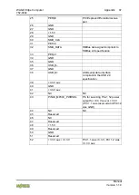
Page 21: ...scription 1 ML_Lane 0 p 2 GND 3 ML_Lane 0 n 4 ML_Lane 1 p 5 GND 6 ML_Lane 1 n 7 ML_Lane 2 p 8 GND 9 ML_Lane 2 2 10 ML_Lane 3 p 11 GND 12 ML_Lane 3 n 13 CONFIG1 14 CONFIG2 15 AUX CH p 16 GND 17 AUX CH...

Page 22: ...Manual Version 1 1 0 4 4 RTC Battery The RTC battery RTC Real Time Clock type BR2032 3 VDC is installed internally and not accessible The RTC battery ensures that the system clock and BIOS settings ar...

Page 23: ...t and whether the product has booted Table 8 PWR LED LED Display Meaning Orange Supply voltage available Green System restarted 4 5 2 HDD LED The HDD LED indicates read write access to the flash memor...

Page 24: ...on in the BIOS Chipset Sout Bridge Restore AC power loss Restore AC power loss Power off ATX mode default BIOS version J1 14 Power on AT mode Last State default BIOS version J1 15 Option 2 Configurati...

Page 25: ...PWR1 ON OFF Button CN25 RJ 45 connector CN18 2 x USB 2 0 connections CN19 USB 3 0 and USB 2 0 connections CN35 DisplayPort connection CN30 Internal power connection 24 VDC 58 50 10 36 V MINI2 mPCIe m...

Page 26: ...mental Conditions Table 13 Technical Data Climatic Environmental Conditions Permissible ambient temperatures 20 60 C Permissible storage temperature 40 85 C Relative humidity without condensation 95 O...

Page 27: ...echnical Data Communication Protocols ETHERNET TCP IP DHCP DNS FTP FTPS HTTP HTTPS und SSH 4 8 7 Interfaces Table 18 Technical Data Interfaces Hardware ETHERNET Interfaces 2 RJ 45 10 100 1000 Mbit s c...

Page 28: ...ns UL62368 FCC Verification per FCC 15 Detailed information regarding approvals Detailed information regarding approvals can be found at https www wago com item no 4 10 Standards and Guidelines The pr...

Page 29: ...passwords to meet your particular needs 5 1 2 Services and Users All password protected services and their associated users are listed in the following table Table 20 Services and Users User Service...

Page 30: ...ord Enter wago as the default password You are prompted to assign a New password Enter a unique password that meets the required level of security and press Enter You are prompted to Retype password E...

Page 31: ...t of machines DIN EN 50178 Electronic equipment for use in power installations replacement for VDE 0160 EN 60439 Low voltage switchgear and controlgear assemblies 6 2 Mounting position Nominal mountin...

Page 32: ...product is intended for installation in control cabinets or housings complying with UL type 1 type 12 or type 4X To ensure adequate cooling and a suitable cable route a free space of 100 mm 3 94 in m...

Page 33: ...Version 1 1 0 7 Connecting 7 1 Grounding Grounding is through the grounding screw on the front side 7 2 Connecting the Supply Voltage Connect the power supply to connector X9 pin 1 and 2 Use the incl...

Page 34: ...uration changed In Firmware 01 the ETHERNET interface X1 is preset to DHCP and the Interface X2 is set with the default IP 192 168 1 17 8 1 Login The system is pre set with two users Table 23 Default...

Page 35: ...pit The HTML pages hereinafter referred to as pages of the Cockpit visualization tool Web Based Management are used to configure the computer To access the Cockpit via a Web browser proceed as follows...

Page 36: ...ner root root Accounts edge root root Services edge root root Updates edge root root Applications edge root root License edge root Terminal edge root edge root Dashboard CPU edge root root Storage edg...

Page 37: ...graphical user interface for Debian Linux is installed 4 Reboot the Edge computer with the command reboot The product boots with the graphical user interface Perform a local configuration ex works in...

Page 38: ...940x Manual Version 1 1 0 9 Removal 9 1 Removal from the Rail 2 To remove pull down the latch Use a screwdriver or an operating tool for this 2 Slide the product out at the lower edge of the rail Figu...

Page 39: ...0 2 2 5 SSD HDD A 2 5 SSD HDD can be used to expand storage space Open the housing by loosening the two screws on the left side of the housing Remove the side panel and install the hard drive on the i...

Page 40: ...em and the Cockpit web based visualization interface are subject to the GNU General Public License For information on the GNU license see http www gnu de documents gpl 2 0 de html https www gnu org li...

Page 41: ...rring it to another computer or user For the purpose of this Terms Computer does also include Controller or Embedded Devices For the installation on a different computer the User might need WAGO s sup...

Page 42: ...s and DIN standards WAGO is not responsible for incorrect or incomplete entries or for incorrect material or component selection for use of the WAGO software WAGO software it not suitable for the use...

Page 43: ...ntext of his acquired licenses For this purpose the User shall provide necessary information to WAGO and provide access to relevant documents and records as well as allow a review of the hardware and...

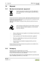
Page 44: ...rom harmful substances in electrical and electronic equipment Observe national and local regulations for the disposal of electrical and electronic equipment Clear any data stored on the electrical and...

Page 45: ...0 Observe national and local regulations for the disposal of packaging Dispose of packaging of all types that allows a high level of recovery reuse and recycling Improper disposal of packaging can be...

Page 46: ...aux 3 3 V PCI 1 1 was 3 3 V PCI 1 2 was 3 3 V aux 3 NC NC 4 GND 5 NC NC 6 1 5 V 7 CLKREQ Reference clock request signal 8 NC NC 9 GND 10 NC NC 11 REFCLK 12 NC NC 13 REFCLK 14 NC NC 15 GND 16 NC NC 17...

Page 47: ...ion 33 PETp0 34 GND 35 GND 36 USB_D 37 GND 38 USB_D USB serial data interface compliant to the USB 2 0 specification 39 3 3 V aux 40 GND 41 3 3 V aux 42 NC NC 43 PIN43_MPCIE_PWRSEL Pin for selecting P...

Page 48: ...940x Manual Version 1 1 0 List of Figures Figure 1 Front view 17 Figure 2 Circuit Diagram 25 Figure 3 Example for Linux Password 30 Figure 4 Terminal Login Screen 35 Figure 5 Cockpit Login Screen 36...

Page 49: ...LED 23 Table 11 Circuit Diagram Legend 25 Table 12 Technical Data Device 26 Table 13 Technical Data Climatic Environmental Conditions 26 Table 14 Technical Data Power Supply 26 Table 15 Technical Dat...

Page 50: ...WAGO Kontakttechnik GmbH Co KG Postfach 2880 D 32385 Minden Hansastra e 27 D 32423 Minden Phone 49 571 887 0 Fax 49 571 887 844169 E Mail info wago com Internet www wago com...

Reviews: