


WAGO-I/O-SYSTEM 750
Process Image 31
750-496 8AI 0/4-20mA S.E.
Manual
Version
1.2.2
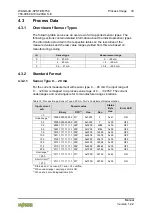
4.1
Overview
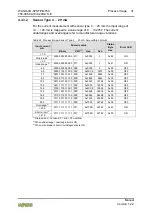
Presentation of control/status bytes a function of fieldbus
coupler/controller!
The I/O module always makes its complete process image incl. control/status
bytes available to the fieldbus coupler/controller. The
WAGO-I/O-
CHECK
commissioning tool accesses the complete commissioning process image. The
fieldbus coupler/controller uses a different process image to stage cyclic process
data via the fieldbus. In the other process image, depending on the fieldbus
coupler/controller, the representation of control/status bytes can be suppressed.
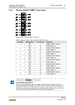
Table 17: Process Image – I/O Module 750-496
Process Image
Input
1)
Output
2)
Byte 0
Status byte CH1_S0
Byte 0
Control byte CH1_C0
Byte 1
Function of status byte: Process
value CH1_D0
Byte 1
Function of control byte:
Reserved
Byte 2
Function of status byte: Process
value CH1_D1
Byte 2
Function of control byte:
Reserved
Byte 3
Control byte CH2_S1
Byte 3
Control byte CH2_C1
Byte 4
Function of status byte: Process
value CH2_D0
Byte 4
Function of control byte:
Reserved
Byte 5
Function of status byte: Process
value CH2_D1
Byte 5
Function of control byte:
Reserved
…
…
…
…
Byte 21 Status byte CH8_S7
Byte 21 Control byte CH8_C7
Byte 22 Function of status byte: Process
value CH8_D0
Byte 22 Function of control byte:
Reserved
Byte 23 Function of status byte: Process
value CH8_D1
Byte 23 Function of control byte:
Reserved
1)
CHx_Sx = Status byte x from channel x
CHx_D0 = Low byte for process value for channel x
CHx_D1 = High byte for process value for channel x
2)
CHx_Cx = Control byte x from channel x