


2787-2147 (/0000-00x0)
Connection
34
Product manual | Version: 1.2.2
Power Supply Pro 2
Note
Only connect one conductor to each CAGE CLAMP
®
connection!
Only one conductor may be connected to each CAGE CLAMP
®
connection. Do not con-
nect more than one conductor on one single connection.
If more than one conductor must be routed to one connection, these must be connected
in an up-circuit wiring assembly, for example, using WAGO Through Terminal Blocks.
To connect the conductors, use an operating tool (see section Accessories) or an appro-
priate screwdriver.
Perform the following steps to make the connection:
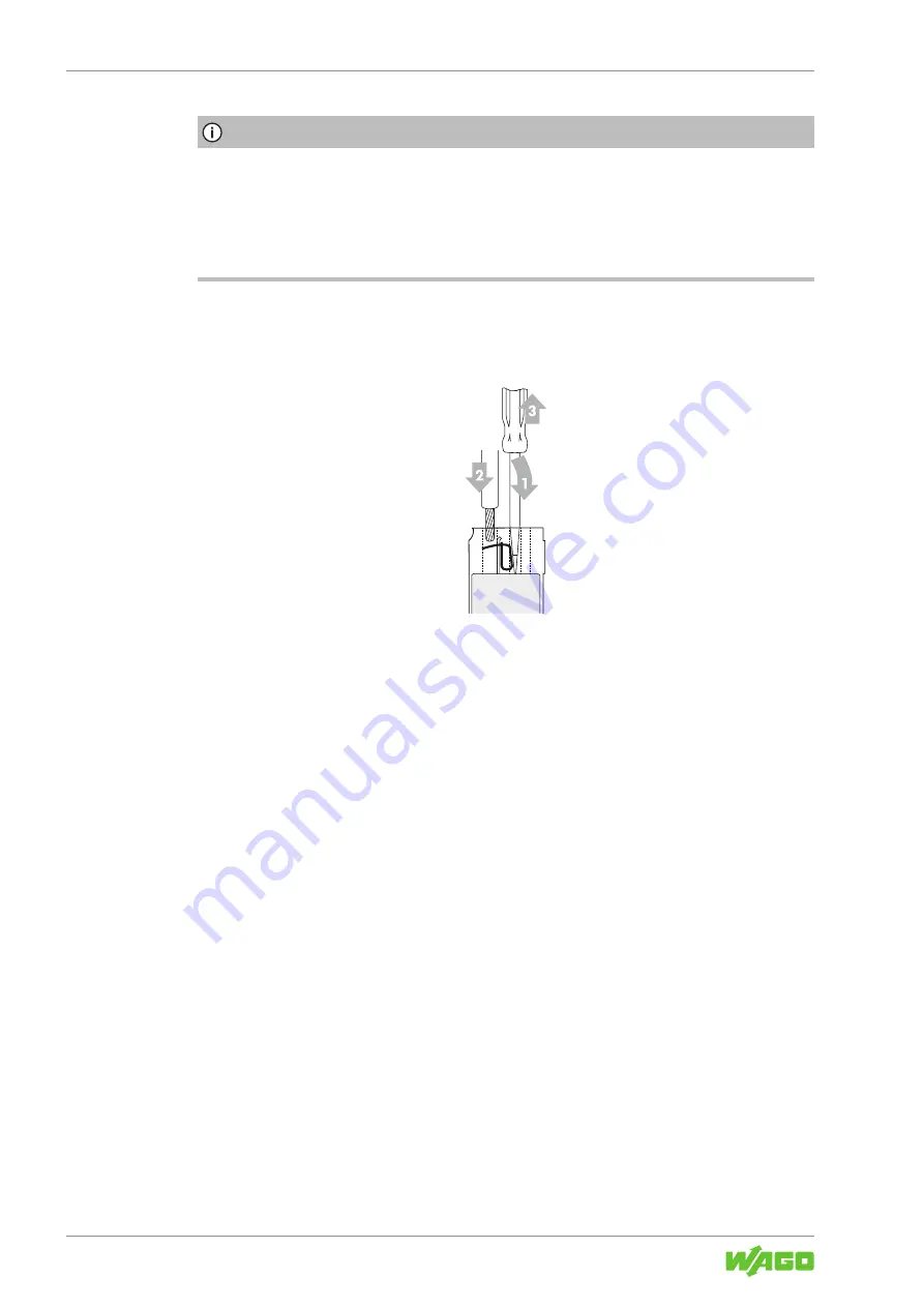
Figure 17: Connect Conductor to CAGE CLAMP®
1. To open the CAGE CLAMP
®
, insert the operating tool into the opening above the
connection.
ð
Once you hear a click, the CAGE CLAMP
®
is open.
2. Insert the conductor into the corresponding connection opening.
3. Remove the operating tool to close the CAGE CLAMP
®
.
ð
The conductor is now securely clamped.
7.3 Push-In Termination
The connection for the output (see section
8
) can also be wired directly.
You do not need any tools for this.
The following conductors can be inserted directly:
• Fine-stranded conductors with ferrules and plastic collars for all permissible cross-sec-
tions
• Fine-stranded conductors with ferrules without plastic collars with a cross-section
> 0.5 mm²/AWG 20
• Solid conductors with a cross-section > 0.5 mm²/AWG 20


