background image

41

Super Finish 23 Pro


  6

  1

  2

  3

  7

  9

  10

  8

  4

  5

  12

  9

  14

11

  4

  15

  16

  13

GB

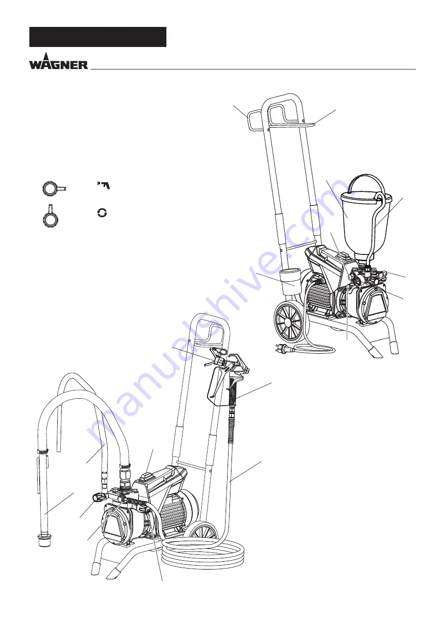
DESCRIPTION OF UNIT

3.3 

EXPLANATORY DIAGRAM

1  Tip guard with airless tip*

2  Spray gun*

3  High-pressure hose*

4  Connection for high-pressure hose

5  Pressure gauge*

6  Pressure control valve

7  ON / OFF switch

8  Pressure relief valve   

=


Spraying

=


Circulation

9  Return hose*

10  Suction hose* 

11 Hopper* 

12  Outlet valve

13  Oil dipstick

14  Cleaning Container

15  Hose bracket

16  Gun holder

17  Tool bag (no fig.)
*Accessory. The actual scope of the delivery 

depends on how the Spray Pack is configured.

Summary of Contents for SF 23 PRO

Page 1: ...SUPER FINISH 23 PRO AIRLESS HIGH PRESSURE SPRAYING UNIT ORIGINALBETRIEBSANLEITUNG wagner group com D GB F E D Betriebsanleitung 2 GB Operating manual 35 F Mode d emploi 66 E Manual de instrucciones 98...

Page 2: ...e with the operating manual before every start up 1 Faulty units may not be used 2 Secure a Wagner spray gun with the securing lever at the trigger guard 3 Ensure earthing 4 Check the permissible oper...

Page 3: ...em______________________ 43 4 2 Unit with upper hopper_______________________ 43 4 3 High pressure hose and spray gun_______________ 43 4 4 Connection to the mains network_______________ 43 4 5 Cleani...

Page 4: ...etc in the vicinity 1 4 DANGER OF INJURY FROM THE SPRAY JET Attention danger of injury by injection Never point the spray gun at yourself other persons or animals Never use the spray gun without spra...

Page 5: ...se can cause sparks and flames upon discharge The unit must therefore always be earthed via the electrical system The unit must be connected to an appropriately grounded safety outlet An electrostatic...

Page 6: ...d latex paints No other materials should be used for spraying without WAG NER s approval Pay attention to the Airless quality of the coating materials to be processed The unit is able to process coati...

Page 7: ...es of finest atomisa tion cloudless operation depending of a correct unit adjust ment and a smooth bubblefree surface As well as these the advantages of the speed of work and convenience must be menti...

Page 8: ...se 4 Connection for high pressure hose 5 Pressure gauge 6 Pressure control valve 7 ON OFF switch 8 Pressure relief valve Spraying Circulation 9 Return hose 10 Suction hose 11 Hopper 12 Outlet valve 13...

Page 9: ...pe from the connec tions 3 5 TECHNICAL DATA Voltage 230 240 V AC 50 Hz Fuses 16 A time lag Unit connecting line 6 m long 3 x 1 5 mm Max current consumption 7 0 A Degree of protection IP 54 Rated input...

Page 10: ...gun align tip and tighten union nut When unscrewing the high pressure hose hold firmly on the hose connection with a 22mm wrench 4 2 UNIT WITH UPPER HOPPER 1 Ensure that the sealing surfaces of the c...

Page 11: ...on tube 1 Immerse the suction system into a container filled with coating material Unit with hopper 2 Fill coating material into the hopper 3 Set pressure relief valve 1 to circulation 4 Switch the de...

Page 12: ...ig B Hold the spray gun at right angles to the surface Otherwise the coating will be thicker at one end than the other Fig C Pull the trigger guard once you have started the movement Release the trigg...

Page 13: ...ong the outside of the scaf folding The risk of damage rises with the age of the high pressure hose Wagner recommends replacing high pres sure hoses after 6 years Only use WAGNER original high pressur...

Page 14: ...ing a metal container Caution Do not pump or spray in container with small opening bunghole See safety regulations 8 Set pressure relief valve to circulation 9 Pump suitable cleaning agent in the circ...

Page 15: ...8 3 HIGH PRESSURE FILTER 1 Set pressure relief valve to pressure relief circulation 2 Switch the unit off using the ON OFF switch Pos 0 3 Open the high pressure filter and clean the filter insert To...

Page 16: ...ross the entire length Have all the electric tests carried by the Wag ner Service The risk of damage rises with the age of the high pressure hose Wagner recommends replacing high pres sure hoses after...

Page 17: ...fully 6 Clean the valve seat 4 with a cleaning agent and brush ensure that no brush hairs are left behind 7 Clean the seals 5 6 and check for damage Replace if necessary 8 Check all the valve parts fo...

Page 18: ...Check the installation position when mounting the spring support ring 3 clipped onto spring 2 outlet valve seat 5 and seal 6 refer to figure Please also pay particular attention to the following notes...

Page 19: ...h proof plug may be used 5 Connect the green yellow wire to the contact with the PE sign 6 Remount the covers carefully do not squeeze any cables 10 5 TYPICAL WEAR PARTS Despite the use of high qualit...

Page 20: ...low blue light blue brown MOTOR WITH TEMPERATURE SWITCH M 1 Z2 U2 OPERATION CAPACITOR C 25 F 400V black 155 C N L Z1 red green yellow blue black N MOTOR SWITCH 8A b U P1 P2 6 3 light blue blue black 3...

Page 21: ...does not gener ate pressure Unit has sucked in Air in the oil circuit Possible reasons long time not used replace ment of diaphragm or hydraulic oil change Vent the hydraulic system see 4 6 Unit reac...

Page 22: ...irCoat controler set 0340 250 5 HP hose DN6 PN270 1 4 NPSM 15m 9984 574 6 Hopper 5l 0341 265 7 Pole gun Length 120cm G thread 7 8 Length 200cm G thread 7 8 0296 441 0296 442 8 Inline Roller 0345 010 I...

Page 23: ...pplication Tip marking Spray angle Bore inch mm Spraying width mm 1 Gun filter Order no Synthetic resin paints PVC paints 211 311 411 20 30 40 0 011 0 28 0 011 0 28 0 011 0 28 120 150 190 red red Rot...

Page 24: ...0553413 0553513 0553613 0553813 Fillers Rust protection paints 115 215 315 415 515 615 715 815 10 20 30 40 50 60 70 80 0 015 0 38 0 015 0 38 0 015 0 38 0 015 0 38 0 015 0 38 0 015 0 38 0 015 0 38 0 0...

Page 25: ...white white white white white white white white white white white white white white white white white white white white white white white white 0553225 0553325 0553425 0553525 0553625 0553725 0553825...

Page 26: ...der no 0271 064 D7 Nozzles 113 417 Order no 0271 063 L10 Nozzles 208 510 Order no 0271 042 D10 Nozzles 111 419 Order no 0271 045 S10 Nozzles 527 235 Order no 0271 049 Medium L20 Nozzles 210 512 Order...

Page 27: ...9436 Reducing double nipple 13 0340257 Pressure gauge assy AUS 14 2369454 Inlet 15 2388291 Inlet valve housing 16 2369455 Clamp 17 2393043 Inlet valve assy incl pos 18 18 2369458 Sealing ring 19 23930...

Page 28: ...61 Super Finish 23 Pro GB Spare parts diagram SF 23 Pro SPARE PARTS AND ACCESSORIES 1 2 3 4 5 6 8 9 11 7 10 14 15 16 18 17 20 12 21 22 23 25 26 27 28 19 24 30 31 29 13...

Page 29: ...ring 11 0508 748 0508 450 0508 449 Filter insert 60 meshes Optional Filter insert 100 meshes Filter insert 30 meshes 12 9994 245 Pressure spring 11 3 SPARE PARTS LIST HIGH PRESSURE FILTER Spare parts...

Page 30: ...118 Foot damping assy pos 7 9 11 9900118 Hexagon screw 12 2369545 Plate damping 13 9920102 Washer 14 9910208 Hexagon nut 15 2393119 Plate damping assy pos 11 14 16 2369556 Wheel 17 9994950 Wheel cap 1...

Page 31: ...referred to as products are carefully inspected tested and are subject to strict checks under Wagner quality assurance Wagner exclusively issues extended guarantees to commercial or professional user...

Page 32: ...cing or care and or cleaning for errors in the device that have been caused by using accessory parts additional components or spare parts that are not original Wagner parts for products to which modif...

Page 33: ...rasse 22 9450 Altst tten Schweiz Tel 41 71 7 57 22 11 Telefax 41 71 7 57 22 22 wagner wagner group ch F Euromair Antony S A V Ile de France 12 14 av F Sommer 92160 Antony Tel 01 55 59 92 42 Telefax 33...

Reviews: