background image


6


EN-XXX_ECOplus-Solar-Storage_MA-201026-1WA10603

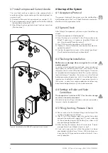
Figure 8  Installation of a CORREX® impressed current anode

3.7 Install a Impressed Current Anode

The installed sacrificial anode can be replaced with a 
maintenance free impressed current anode (optional ac-
cessory, fig  8)  


Remove cable and existing magnesium anode (1), (2) 


Screw impressed current anode and fasten the cable to 
the electronics device (3) - (5) 


After filling the storage tank check function (see chap  
„Maintenance“) 

4 Startup of the System

4.1 Acceptance Protocol

The correct startup of the system must be certified by a 
qualified person in the Final Check Protocol in order ren-
der the warranty agreement valid 

4.2 System Check

After fitting all components, please carry out the following 
checks:


Are all components fitted correctly?


Are all safety units installed? Is the 10 bar safety valve 
fitted? If necessary, is a pressure regulator fitted and 
can it be closed off from the vessel?


Are all fittings and connections safe and tight?


If present – were all electrical connections made to re-
quired standards?


Are the temperature sensors in the correct positions? 
Do all controllers display plausible values?

4.3 Flushing the Installation

Malfunction or damage when storage tank is not ade-
quately purged!

In spite of careful production methods, some residues of 
the processes, including metal slack, may remain inside 
the pipes, the vessel and the heat exchangers  These can 
cause problems during operation of the system and may 
lead to damage  Therefore, the system must be flushed 
before permanent operation starts  Also filtering/retain-
ing devices should be installed at convenient points in 
the system, as even later some production residues may 
become dislodged and may have to be removed 

4.4  Settings at Boiler and Solar 

Controllers

The temperature limitation of 95 °C for the solar storage 
vessel must never be exceeded. 

Observe correct settings at boiler and solar controllers 
(e g  max  boiler temperature) 

4.5 Filling, Venting, Pressure Check


Pease make sure that before filling and startup of the 
system, all openings are closed 


(Fig  9) To fill the storage, open the cock of the safety 
group in the cold water supply leg (17) and a water tap 
of the connected supply  While doing so, allow air to 
escape through the bleed (9) 


After venting the piping close all water taps  If water 
escapes from the air bleed, close it as well 


Carry out a pressure test after the system has been 
completely installed (max  10 bar)  While test pressur-
izing, check all fittings and connections for leaks  If nec-
essary retighten 

1

2

3

4

5

Summary of Contents for ECOplus

Page 1: ...ration 2 3 2 Setting up the Storage 2 3 3 Connecting the Domestic Water Circuit 4 3 4 ConnectingtheSolar andAuxiliary Heating Circuit 5 3 5 Connecting Backup Heater 5 3 6 Installing Temperature Sensors 5 3 7 Install a Impressed Current Anode 6 4 Startup of the System 6 4 1 Acceptance Protocol 6 4 2 System Check 6 4 3 Flushing the Installation 6 4 4 Settings at Boiler and Solar Controllers 6 4 5 Fi...

Page 2: ...the filled tank Wagner Solar cannot be held liable for damages resulting from improper use 2 Scope of supply The ECOplus solar cylinder is supplied standing upright and screwed onto a pallet The serial no is located on the type label Table 1 Scope of supply fig 2 1 Storage 2 Jacket insulation with hook ratchet closure may be several parts depending on storage type 3 Insulation plug with cap for ac...

Page 3: ...EN XXX_ECOplus Solar Storage_MA 201026 1WA10603 3 Figure 2 Scope of supply Figure 3 Tilt the storage to insert the inner floor insulation 2 4 8 7 1 6 5 2 3 ...

Page 4: ...s heated to its maximum tem perature the DHW temperature set at the thermostatic mixing valve will not be exceeded If no thermostatic mixer is fitted maximum vessel temperature must be limited to 65 C at the solar controller Serious danger of scalding Thesolarinstallationmayheatthestoragewatertotem peratures of up to 95 C The installation of a thermostatic mixing valve limits the tap temperatures ...

Page 5: ...available that can be installed in the 1 socket on the side fig 6 Please observe instructions supplied with the respec tive heating device Laying the mains cable of the electrical heater a heat resistant cable min up to 95 C must be used when laying the cable under the insulation jacket The immersion heater must only be connected to mains after the storage tank is filled If no immersion heater is ...

Page 6: ...allation Malfunction or damage when storage tank is not ade quately purged In spite of careful production methods some residues of the processes including metal slack may remain inside the pipes the vessel and the heat exchangers These can cause problems during operation of the system and may lead to damage Therefore the system must be flushed before permanent operation starts Also filtering retai...

Page 7: ...ar cylinder 1 Now set the insulation jacket to the connection side around the connection openings and if in place the immersion heater 2 First lock the ratchet closure into the loosest position and then tighten from the top alternating if the jacket has more than one closure until the jacket tightly fits the storage tank 3 If no immersion heater is fitted insert insulation plug with cap 4 Insert i...

Page 8: ... in uninsulated sacrificial magne sium anode examine remaining magnesium mass and if necessary install new anode Forsacrificialanodeswithinsulatedinstallation MGan odes test the protective current between storage and anode fig 13 When the value is below 0 3 mA remove and examine the anode and replace if required If an impressed current anode is installed observe the related product documentation A...

Reviews: