


EN
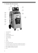
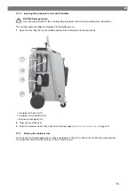
17 Container for fresh oil
18 Container for UV additive (500 ml)
19 Drained oil receptacle
20 Cover flap
21 Main switch
22 Fan
12 Initial start-up
This chapter describes the procedures you have to carry out before you can operate the A/C service unit.
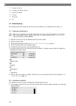
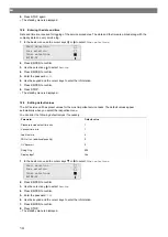
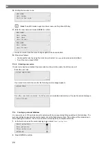
12.1 Setting up and switching on
Note
In order to achieve correct measurements, the A/C service unit must be placed on a level flat sur-
face during operation. Ignore any error codes which occur during commissioning (
page 36) and skip by pressing
ENTER
.
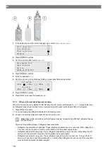
1.
Wheel the A/C service unit to the workplace and lock the front wheels.
2.
Mount the service hoses.
3.
Set the length of the service hoses (
Setting the length of the service hoses
on page 11).
4.
Connect the A/C service unit to the power supply.
5.
To switch the A/C service unit on, set the main switch to
I
.
The switch-on delay runs for 35
s and the housing is ventilated. The software version number then appears in
the display for several seconds:
mgas0081
mgas2107
LE640004
LF
DB
SW
SN000000
LE
ASC6400G
Dometic Germany GmbH
SW:
Software status
DB:
Database
SN:
Serial number
LF:
Language file
6.
Once the start-up procedure is complete, the A/C service unit requires the selection of the refrigerant (
on page 10).
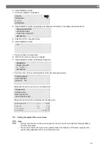
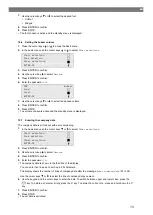
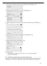
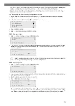
12.2 Selecting the refrigerant
On initial start-up the A/C service unit displays the refrigerant selection menu.
1.
In the refrigerant selection menu use the cursor keys or to select the desired refrigerant (in the following
example R153A).
R-513A
R-1234yf
R-134a
Refrigerant
10
Summary of Contents for ASC 6300 G
Page 9: ...EN 16 USB port 9...
Page 41: ...EN 17 1 Flowchart ASC6300 G Legend 41...
Page 44: ...EN 17 2 Flowchart ASC6400 G Legend 44...
Page 47: ...EN 17 3 Circuit diagram ASC6300 G 47...
Page 48: ...EN 48...
Page 49: ...EN 17 4 Circuit diagram ASC6400 G 49...
Page 50: ...EN 50...
Page 58: ...FR 16 Port USB 58...
Page 92: ...FR 17 1 Organigramme ASC6300 G L gende 92...
Page 95: ...FR 17 2 Organigramme ASC6400 G L gende 95...
Page 98: ...FR 17 3 Sch ma lectrique ASC6300 G 98...
Page 99: ...FR 99...
Page 100: ...FR 17 4 Sch ma lectrique ASC6400 G 100...
Page 101: ...FR 101...
Page 109: ...DE 16 USB Anschluss 109...
Page 142: ...DE 17 1 Flussdiagramm ASC6300 G Legende 142...
Page 145: ...DE 17 2 Flussdiagramm ASC6400 G Legende 145...
Page 148: ...DE 17 3 Schaltplan ASC6300 G 148...
Page 149: ...DE 149...
Page 150: ...DE 17 4 Schaltplan ASC6400 G 150...
Page 151: ...DE 151...
Page 153: ...RU 4 Tel 49 0 2572 879 0 5 6 Domestic 153...
Page 154: ...RU 6 1 154...
Page 155: ...RU 6 2 R1234yf 405 C R134a 743 C R153A 6 3 155...
Page 157: ...RU Dometic 10 10 1 230 240 50 60 190 10 2 10 3 10 4 157...
Page 158: ...RU 11 1 2 3 4 ECO 5 6 7 8 9 10 11 12 13 14 15 158...
Page 159: ...RU 16 USB 159...
Page 182: ...RU 11 12 ENTER 13 14 15 D 16 E 17 15 18 19 20 R1234yf 179 21 179 14 5 12 182...
Page 184: ...RU 2 D E 3 I 4 G 5 J 6 J 7 H G 8 9 10 179 184...
Page 188: ...RU 181 ENTER 3 183 ENTER 3 01 02 03 04 188...
Page 189: ...RU 09 10 12 52 USB USB USB FAT32 60 61 G1 00001 00002 00003 00004 10 C 45 C 00001 189...
Page 192: ...RU 17 1 ASC6300 G 192...
Page 194: ...RU X23 DO X3 UV X4 X5 Z2 X6 Z2 X7 HP X8 HP X9 RE 194...
Page 195: ...RU 17 2 ASC6400 G 195...
Page 197: ...RU X10 VC X16 CY X2 LP X23 DO X3 UV X4 X5 Z2 X6 Z2 X7 HP X8 HP X9 RE 197...
Page 198: ...RU 17 3 ASC6300 G 198...
Page 199: ...RU 199...
Page 200: ...RU 17 4 ASC6400 G 200...
Page 201: ...RU 201...
Page 209: ...ES 16 Conexi n USB 209...
Page 244: ...ES 17 1 Diagrama de flujo ASC6300 G Leyenda 244...
Page 247: ...ES 17 2 Diagrama de flujo ASC6400 G Leyenda 247...
Page 250: ...ES 17 3 Esquema de conexiones ASC6300 G 250...
Page 251: ...ES 251...
Page 252: ...ES 17 4 Esquema de conexiones ASC6400 G 252...
Page 253: ...ES 253...
Page 254: ...4445103554 2022 11 30...


