background image


3 Safety

Operator's manual

13

Operating company responsibilities

The operating company must make the operator's manual available to the oper-
ator and ensure that the operator has read and understood it.


Work recommendations

Please observe the recommendations below:

„

Work only if you are in a good physical condition.

„

Work attentively, particularly as you finish.

„

Do not operate the machine when you are tired.

„

Carry out all work calmly, circumspectly and carefully.

„

Never operate the machine under the influence of alcohol, drugs or medica-
tion. This can impair your vision, reactions and your judgment.

„

Work in a manner that does not endanger others.

„

Ensure that no persons or animals are within the danger zone.


3.3

Protective gear

Work clothing

Clothing should be appropriate, i.e. should be close-fitting but not restrict your 
movement.
When on construction sites, do not wear long hair loosely, loose clothing or jew-
elry including rings. These objects can easily get caught or be drawn in by mov-
ing machine parts.
Only wear clothing made of material that is not easily flammable.


Personal protective gear

Wear personal protective gear to avoid injuries or health hazards:

„

Non-skid, hard-toed shoes.

„

Work gloves made of durable material.

„

Overalls made of durable material.

„

Hard hat.

„

Ear protection.


„

Face protection.

„

Eye protection.

„

Breathing protection in the case of dusty ambient air.


Summary of Contents for RCE

Page 1: ...Operator s manual Cutting machine RCE 0215051en 003 12 2009 ...

Page 2: ...Manufacturer Wacker Neuson SE Preußenstraße 41 80809 München www wackerneuson com Tel 49 0 89 354 02 0 Fax 49 0 89 354 02 390 Translation of the original operator s manual in German ...

Page 3: ...appliances 16 3 8 Safety during the operation of hydraulic machines 18 3 9 Maintenance 18 3 10 Safety and information labels 19 3 11 Safety devices 20 4 Scope of delivery 21 5 Description 22 5 1 Application 22 5 2 Functionality 22 5 3 Components and operator s controls 23 6 Transport 26 7 Operation 27 7 1 Prior to starting the machine 27 7 2 Adjusting the machine 28 7 3 Starting up 29 7 4 Decomiss...

Page 4: ...ting 41 10 Disposal 42 10 1 Disposal of the machine 42 11 Accessories 43 12 Technical data 44 12 1 RCE 16 20 25 230 44 12 2 RCE 16 20 25 115 45 12 3 RCE 16 20 25 120 46 12 4 Extension cable 47 13 Glossary 51 EC Declaration of Conformity 53 ...

Page 5: ...achine in accordance with the instructions in this operator s manual Your reward will be troublefree operation and a high degree of availability Defective machine parts must be replaced immediately Please contact your Wacker Neuson representative if you have any questions concerning operation or maintenance All rights reserved especially reproduction and distribution rights Copyright 2009 Wacker N...

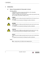
Page 6: ...s warning notice indicates immediate hazards that result in serious injury or even death f Danger can be avoided by the following the actions mentioned WARNING This warning notice indicates possible hazards that can result in serious injury or even death f Danger can be avoided by the following the actions mentioned CAUTION This warning notice indicates possible hazards that can result in minor in...

Page 7: ...euson affiliate or your Wacker Neuson dealer You can find the addresses in the Internet at www wackerneuson com The address of the manufacturer is located at the beginning of this operator s manual 2 3 Described machine parts This operator s manual is valid for different machine parts from a product range Therefore some figures can differ from the actual appearance of your machine It is also possi...

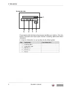
Page 8: ...identifies your machine This infor mation is needed to order spare parts and when requesting additional technical information f Enter the information of your machine into the following table Item Designation Your information 1 Group and type 2 Construction year 3 Machine no 4 Version no 5 Item no ...

Page 9: ...he machine design Please refer to the chapter Technical Data for information concerning your machine Worksites are construction sites and operations which fabricate reinforcements or process reinforcing iron The machine may only be used for legal and permit ted purposes The machine must not be used for processing the following materials Wires Pipes Plastics Wood Its proper use also includes the ob...

Page 10: ...no problem to install accessories that are available in the Wacker Neuson product range of your machine Please refer to the installation regulations in this operator s manual Do not drill into the housing e g to install signs Water could penetrate the hous ing and damage the machine Requirements for operation The ability to operate the machine safely requires Proper transport storage and setup Car...

Page 11: ...gn and quality Only use accessories from Wacker Neuson Non compliance will exempt the manufacturer from all liability Exclusion of liability Wacker Neuson will refuse to accept liability for injuries to persons or for damage to materials in the following cases Structural modifications Improper use Failure to comply with this operator s manual Improper handling Using of spare parts which are not fr...

Page 12: ...f for any signs of damage at least once per work shift Do not operate the machine if there is visible damage or defects Have any damage or defects eliminated immediately 3 2 Qualification of the operating personnel Operator qualifications Only trained personnel are permitted to start and operate the machine The fol lowing rules also apply You are physically and mentally fit You have received instr...

Page 13: ...our judgment Work in a manner that does not endanger others Ensure that no persons or animals are within the danger zone 3 3 Protective gear Work clothing Clothing should be appropriate i e should be close fitting but not restrict your movement When on construction sites do not wear long hair loosely loose clothing or jew elry including rings These objects can easily get caught or be drawn in by m...

Page 14: ...o prevent it from toppling falling or slipping away Restarting Machines machine parts accessories or tools that were detached for transport purposes must be re mounted and fastened before restarting Only operate in accordance with the operating instructions 3 5 Operating safety Explosible environment Never operate the machine in a potentially explosive environment Work environment Familiarize your...

Page 15: ... that you stand firmly when working with the machine This ap plies particularly when working on scaffoldings ladders uneven or slippery floors etc Caution with movable parts Keep your hands feet and loose clothing away from moving machine parts No persons endangered Be sure that no persons are endangered by flying or falling materials Always work very attentively and anticipate potential hazards S...

Page 16: ...uring the operation of electric appliances Specific regulations for electrical appliances Observe the safety information provided in the brochure General Safety Rules which is included in the scope of delivery of your machine Also observe the country specific regulations standards and guidelines in refer ence to accident prevention in connection with electrical equipment and ma chines WARNING Read...

Page 17: ...he respective national safety regulations Extension cable The machine may only be operated with undamaged and tested extension ca bles Only use extension cables with grounded conductor and correct connection of the grounded conductor to the plug and coupling only for machines of class rat ing I see chapter Technical data Only use tested extension cables which are suitable for use at construction s...

Page 18: ...of hydraulic machines Hydraulic oil Hydraulic oil is harmful to health Wear safety glasses and safety gloves when handling hydraulic oil Avoid direct skin contact with hydraulic oil Remove hydraulic oil from the skin im mediately with soap and water Make sure that no hydraulic oil comes gets in the eyes or on the body See a phy sician immediately if hydraulic oil gets into the eyes or is swallowed...

Page 19: ... present this can pose a serious injury risk from electric shocks 3 10 Safety and information labels Your machine has adhesive labels containing the most important instructions and safety information Make sure that all the labels are kept legible Replace any missing or illegible labels The item numbers for the labels are in the parts book Label Description Wear safety glasses Wear hard hat Follow ...

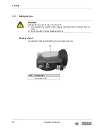
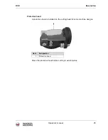
Page 20: ...d A protective hood is installed for some machine designs WARNING Danger of injury due to open moving parts f Only operate the machine with properly installed and functioning safety de vices f Do not modify or remove safety devices Item Designation 1 Protective hood ...

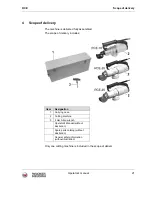
Page 21: ...sembled The scope of delivery includes Only one cutting machine is included in the scope of deliver Item Designation 1 Carrying case 2 Cutting machine 3 4 mm Allen wrench Operator s Manual without illustration Spare parts catalog without illustration General safety information without illustration ...

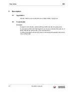
Page 22: ... Functionality Principle An electric motor drives a piston with thrust bolt forwards via a gear pump A valve opens at the end of the forward movement and releases the pressure A spring presses the piston back in the original position In cutting operating the thrust bolt moves a moveable knife against a fixed knife in the cutting head ...

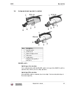
Page 23: ...F switch As long as the ON OFF switch is pressed the machine runs in cutting operation Switching off the machine If the ON OFF switch is released the motor stops The movable knife stops in the current position Item Designation 1 ON OFF switch 2 Oil filler neck 3 Pressure release screw 4 Stop screw 5 Cutting head Protective hood without illustration ...

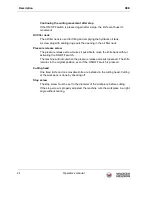
Page 24: ... release screw makes it possible to move the knife back without activating the ON OFF switch The machine will not cut when the pressure release screw is loosened The knife remains in the original position even if the ON OFF switch is pressed Cutting head One fixed knife and one movable knife are installed in the cutting head Cutting of the workpiece is done by shearing off Stop screw The stop scre...

Page 25: ...ption Operator s manual 25 Protective hood A protective hood is installed on the cutting head for some machine designs Close the protective hood before cutting to avoid injuries Item Designation 1 Protective hood ...

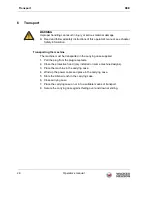
Page 26: ...hine in the carrying case 4 Wind up the power cable and place in the carrying case 5 Store the Allen wrench in the carrying case 6 Close carrying case 7 Place the carrying case on or into a suitable means of transport 8 Secure the carrying case against falling over and down or sliding WARNING Improper handling can result in injury or serious material damage f Read and follow all safety instruction...

Page 27: ...g voltage see nameplate of the machine or chapter Technical Data f Check if mains or power distribution on the constructions site are protected in accordance with current standards and regulations WARNING Improper handling can result in injury or serious material damage f Read and follow all safety instructions of this operator s manual see chapter Safety information WARNING Movable knives Body pa...

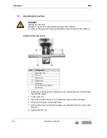
Page 28: ...e machine designs 4 Place the workpiece on the fixed knife 5 Set the stop screw so that the workpiece is perpendicular to the axis of the machine 6 Tighten the jam nut WARNING Starting the machine Danger of injuries from uncontrolled starting of the machine f Remove the plug from the plug receptacle before all work on the machine Item Designation 1 Movable knife 2 Jam nut 3 Stop screw 4 Fixed knif...

Page 29: ...t the plug into the plug receptacle NOTICE Worn out knives Premature wear of the machine f Before beginning work check the sharpness of the knife visually f Change worn out knives NOTICE Electrical voltage Incorrect voltage can cause damage on the machine f Check if the voltage of the current source corresponds with the information of the machine see chapter Technical Data CAUTION Electrical volta...

Page 30: ...rom insufficiently guided or uncontrolled machine Body parts could be cut off f If the machine is guided to the workpiece the machine must always be held tight with both hands and stand securely f If the machine is on a stable foundation hold the machine with one hand on the handle and hold the workpiece with the other hand NOTICE Incorrect placement Premature wear of the knife f Make sure that th...

Page 31: ...ne 1 Release ON OFF switch 2 Pull the plug from the plug receptacle Cleaning the machine 1 Free the cutting head of cutting residues with suitable tools 2 Wipe the housing with a damp and clean cloth CAUTION Electrical voltage Danger of electrocution f Make sure when cleaning that no water gets into the machine Do not clean machine under running water or with a high pressure cleaner ...

Page 32: ...le before all work on the machine Task Daily before operation As required Every 2 years Check power cable for perfect condition if power cable is defective have it replaced Have these tasks carried out by the service department of your Wacker Neuson contact person Visual inspection of all parts for damage Check knife for wear if necessary replace knife Check screws on machine for tightness if nece...

Page 33: ...uction site A level and clean work surface makes work easier There is a better overview over small parts and they are not lost as easily 8 2 1 Visual inspection for damage Checking the machine f Check all machine parts for damage or cracks WARNING A damaged machine part or power cable can result in personal injury caused by electric current f Do not operate a damaged machine f Have a damaged machi...

Page 34: ...he thrust bolt For this press the ON OFF switch 2 Pull the plug from the plug receptacle 3 Open the protective hood only installed on some machine designs Changing the fixed knife 1 Screw out the fastening screw 2 Changing fixed knife 3 Tighten the fixed knife with the fastening screw Item Designation 1 Fastening screw 2 Fixed knife ...

Page 35: ...nd the hole in the cutting head are in aligned For this press the ON OFF switch 2 Pull the plug from the plug receptacle 3 Open the protective hood only installed on some machine designs Changing the movable knife 1 Screw out the fastening screw 2 Changing movable knife 3 Tighten the movable knife with the fastening screw Item Designation 1 Movable knife 2 Fastening screw ...

Page 36: ...oil is hot f Let machine cool off CAUTION Hydraulic oil under pressure Squirting hydraulic oil can penetrate the skin f Only unscrew the screw plug on the oil filler neck if the thrust bolt is completely extended f Wear safety glasses and protective gloves NOTICE Wrong hydraulic oil Damage to machine f Only fill with hydraulic oils which are specified for the machine in the chapter Technical Data ...

Page 37: ...he screw plug on the oil filler neck slowly and carefully Hold a cloth over the oil filler neck with the second hand for protection against escaping hydraulic oil 3 Unscrew the screw plug on the oil filler neck and remove with sealing ring 4 Check if the hydraulic oil reaches to the lower edge of the oil filler neck If necessary fill with hydraulic oil up tot the lower edge of the oil filler neck ...

Page 38: ... 2 Screw plug 3 Oil filler neck WARNING Hot hydraulic oil Injury by scalding f Do not open the screw plug on the oil filler neck as long as the hydraulic oil is hot f Let machine cool off CAUTION Hydraulic oil under pressure Squirting hydraulic oil can penetrate the skin f Only unscrew the screw plug on the oil filler neck if the thrust bolt is completely extended f Wear safety glasses and protect...

Page 39: ...e with sealing ring 4 Hold the machine with the oil filler neck over the collection container and drain hydraulic oil 5 Loosen the pressure release screw until the thrust bolt retracts 6 When the thrust bolt is completely retracted tighten the pressure release screw 7 Drain the remaining hydraulic oil completely into the collection container Note Dispose of hydraulic oil according to the applicabl...

Page 40: ...ompletely extend the thrust bolt 4 Pull the plug from the plug receptacle Top up with hydraulic oil 1 Place the machine so that the oil filler neck points vertically upward 2 Unscrew the screw plug on the oil filler neck and remove with sealing ring 3 Fill with hydraulic oil up to the lower edge of the oil filler neck 4 Screw in the screw plug with sealing ring in the oil filler neck and tighten ...

Page 41: ...arried out by the service department of your Wacker Neuson contact person Thrust bolt does not extend Pressure release screw released Tighten the pressure release screw Thrust bolt moves out incompletely or unevenly Insufficient hydraulic oil in the hydraulic oil tank Check oil level fill with hydraulic oil if necessary Cold hydraulic oil Warm up machine for approx 1 minute Thrust bolt does not mo...

Page 42: ...which should be disposed and recycled in an environmentally friendly manner During disposal of the machine observe the country specific rules and regulations e g the European Directive for obsolete electrical and electronic devices Do not dispose of the machine in household rubbish It must be disposed at a recycling facility ...

Page 43: ...E Accessories Operator s manual 43 11 Accessories The following accessories are offered for the machine For more information on the individual accessories visit the following website www wackerneuson com ...

Page 44: ...ption W 1 200 1 100 1 100 Rated current consumption A 5 8 5 3 5 3 Class rating II Protection class IP 20 Engine speed rpm 10 000 Operating temperature C F 20 to 50 4 to 122 Hydraulic oil specification HLP ISO 46 Hydraulic oil fill quantity l gal 0 6 0 2 Max compressive force t 11 14 31 Opening closing time of the tool s 5 Max allowable tension strength of the workpiece N mm2 750 Max allowable diam...

Page 45: ...100 1 200 1 200 Rated current consumption A 9 2 10 0 10 0 Class rating II Protection class IP 20 Engine speed rpm 10 000 Operating temperature C F 20 to 50 4 to 122 Hydraulic oil specification HLP ISO 46 Hydraulic oil fill quantity l gal 0 6 0 2 Max compressive force t 11 14 31 Opening closing time of the tool s 5 Max allowable tension strength of the workpiece N mm2 685 Max allowable diameter wor...

Page 46: ...100 1 200 1 200 Rated current consumption A 9 2 10 0 10 0 Class rating II Protection class IP 20 Engine speed rpm 10 000 Operating temperature C F 20 to 50 4 to 122 Hydraulic oil specification HLP ISO 46 Hydraulic oil fill quantity l gal 0 6 0 2 Max compressive force t 11 14 31 Opening closing time of the tool s 5 Max allowable tension strength of the workpiece N mm2 685 Max allowable diameter wor...

Page 47: ...or the type designation and voltage rating of your machine WARNING Electrical voltage Injuries from electrocution f Check power cable and extension cable for signs of damage f Only use extension cables for which grounded conductors are connected to the plug and the coupling only for machines of class rating I see chapter Technical Data Machine Voltage V Extension m Cross section area of cable mm2 ...

Page 48: ...Technical data RCE 48 Operator s manual RCE 20 25 115 30 1 5 50 2 5 79 4 118 6 120 31 1 5 52 2 5 82 4 122 6 230 113 1 5 150 2 5 Machine Voltage V Extension m Cross section area of cable mm2 ...

Page 49: ...e machine has an input voltage of 230 V According to the table the extension cable must feature a cross section area of 1 5 mm2 AWG 14 Machine Voltage V Extension ft Cross section area of cable AWG RCE 16 115 95 16 148 14 233 12 371 10 120 98 16 154 14 243 12 384 10 230 295 16 469 14 RCE 20 25 115 85 16 138 14 217 12 341 10 120 89 16 141 14 282 12 354 10 230 325 16 492 14 ...

Page 50: ...Technical data RCE 50 Operator s manual ...

Page 51: ...or Plug connection without grounded conductor contact I Connection of all conductive housing components to the grounded conductor Plug connection with grounded conductor contact II Reinforced or double insulation protective insulation No connection to the grounded conductor Plug connection without grounded conductor contact III Machines are operated on protective low voltage 50 V Connection to the...

Page 52: ...n objects diameter 12 5 mm 3 Protected against touch with a tool diameter 2 5 mm Protected against small foreign objects with diameter 2 5 mm 4 Protected against touch with a wire diameter 1 mm Protected against granular foreign objects diameter 1 mm 5 Protected against contact Protected against dust depositing inside 6 Completely protected against any contact Protected from dust Code Meaning 2nd ...

Page 53: ... re quirements of the following guidelines and standards 98 37 EC from 29 12 2009 2006 42 EC 2006 95 EC 2004 108 EC EN 61000 EN 55014 Authorized person for technical documents Axel Häret Munich 03 04 2009 Type RCE 16 RCE 20 RCE 25 Product type Cutting machine Item no 0610207 0610208 0610218 0610209 0610210 0610219 0610211 0610212 0610220 Dr Michael Fischer Head of Research and Development Franz Be...

Page 54: ......

Page 55: ......

Page 56: ......

Reviews: