5-54
BA E16 en* 1.0 * E16_10_510.fm
5 Operation
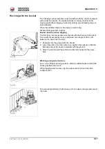
Hydraulic thumb control circuit (option)
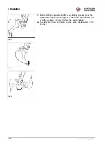
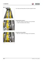
The change-over takes place on the left and right at the end of the stick.
Position the arm system straight ahead at the center of the vehicle
(
).
Lower the boom and the stabilizer blade to the ground.
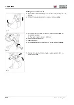
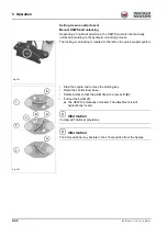
Setting the hydraulic thumb:
Bring the ball-type cock
A
with lever
B
into the desired position to the left
and right on the stick.
Information
The lever must be removed before operation.
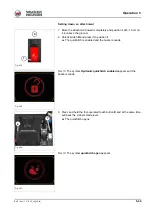
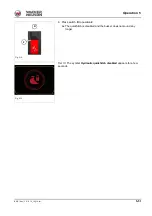
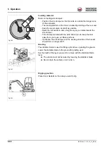
The operation occurs via the right joystick
Fig. 220 (Symbol representation)
Fig. 221
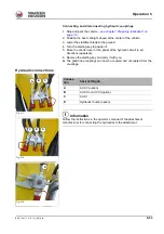
1
A
B
C
Position of the slot C
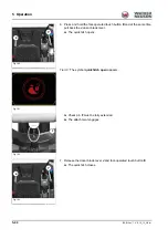
Operating
1
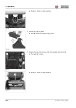
AUX I
2
Hydraulic thumb
Fig. 222
2
A
B
C
Summary of Contents for ET35
Page 14: ...1 8 BA E16 en 1 0 E16_10_100 fm 1 Foreword Notes...
Page 46: ...3 8 BA E16 en 1 0 E16_10_300 fm 3 Introduction Warning labels Fig 9 symbolic representation...
Page 64: ...3 26 BA E16 en 1 0 E16_10_300 fm 3 Introduction Notes...
Page 194: ...6 8 BA E16 en 1 0 E16_10_600 fm 6 Transportation Notes...
Page 252: ...8 8 BA E16 en 1 0 E16_10_800 fm 8 Malfunctions Notes...
Page 292: ...9 40 BA E16 en 1 0 E16_10_900 fm 9 Technical data 9 15 Dimensions ET35 symbolic representation...
Page 294: ...9 42 BA E16 en 1 0 E16_10_900 fm 9 Technical data EZ36 symbolic representation...
Page 296: ...9 44 BA E16 en 1 0 E16_10_900 fm 9 Technical data Notes...
Page 300: ...S 4 BA E16 en 1 0 E16_10_3SIX fm...

